ABB Power Distribution 53
Figure 6/7: Control wiring plug connector blocked to prevent
disconnection with the withdrawable breaker part in the
service position
10.1 Control wiring socket
10.2 Control wiring plug
32 Interlock
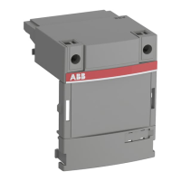
Figure 6/8: Handling of the mechanical circuit-breaker operation in
the panel door (non-standard equipment) with the
withdrawable part in the service position
45.1 Mechanical push-button
45.2 Knob
45.1
45.2
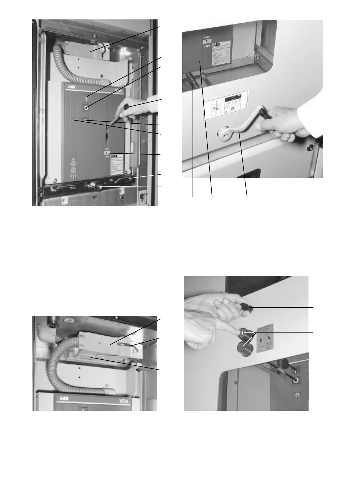
Figure 6/5: Manual operation and mechanical indicators of a circuit-
breaker withdrawable part, vacuum circuit-breaker
withdrawable part in test/disconnected position
10 Control wiring plug connection, closed
13.2 Mechanical ON push-button
13.3 Mechanical OFF push-button
13.4 Mechanical position indicator
13.5 Mechanical operating cycle counter
13.8 Charging condition indicator
13.11 Sliding handle, connected to the catch in the
withdrawable part base frame
(18) Spindle mechanism
18.1 Square spigot
128 Charging lever
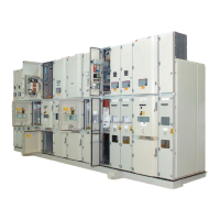
Figure 6/6: Movement of the withdrawable breaker part between
the test/disconnected position and the service position,
with approx. 20 turns of the crank, clockwise up to the
stop for the service position and anti-clockwise for the
test/disconnected position
13 Withdrawable breaker part
18 Spindle mechanism
121 Hand crank
18 13 121
10
13.2
13.3
128
13.8
13.4
13.5
13.11
(18)/
18.1
10.2
10.1
32