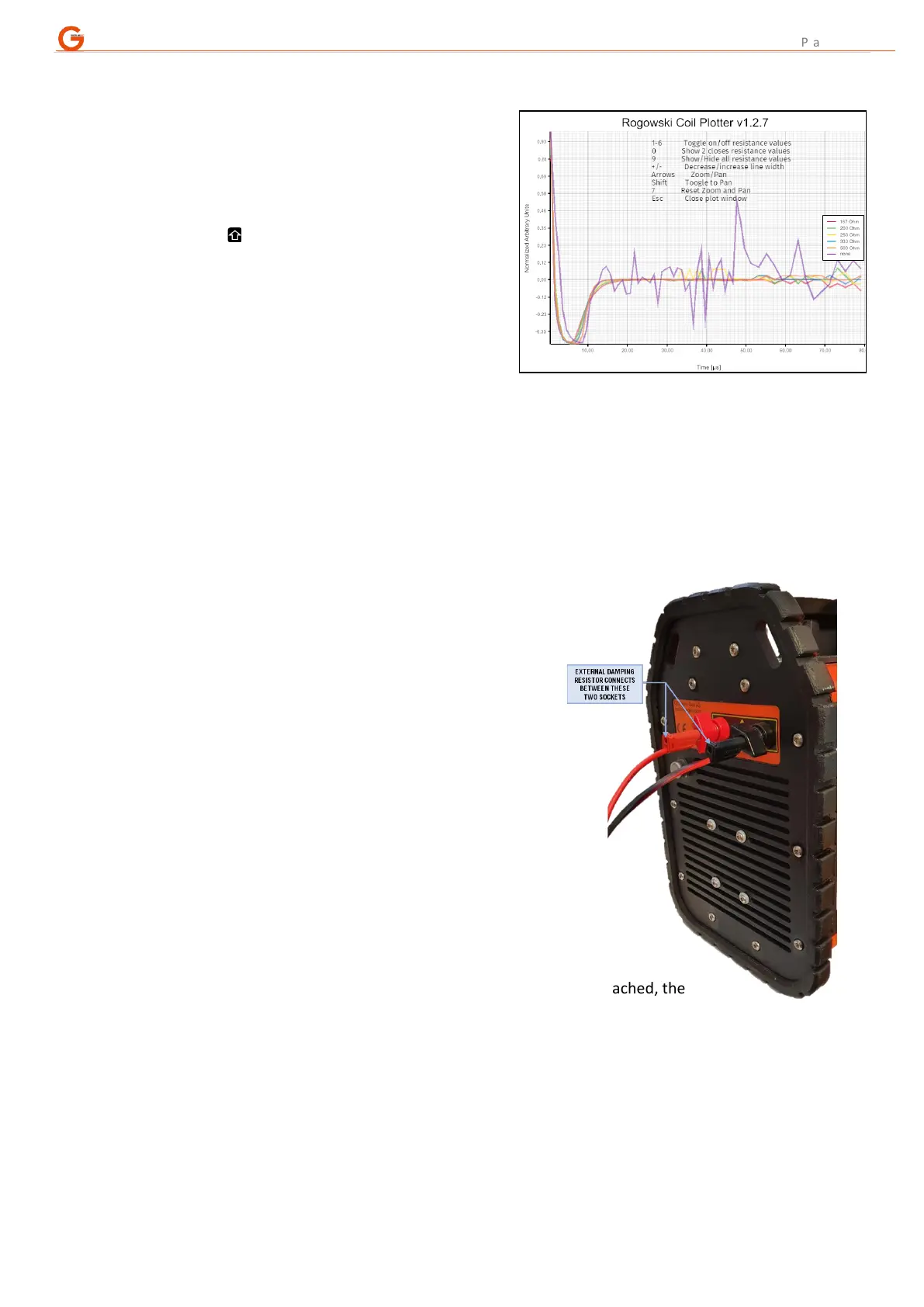
C. Once the test measurements have finished, plot the data and choose the best resistor:
- hit “Plot” and a new window will open showing the
resulting curves;
- the time axis is in real units but the decay curves
are normalized within the current zoom level to
arbitrary units;
- the arrow keys allow panning and zooming with the
“Shift” key ( ) toggling between the two functions;
- keys 1 to 6 will switch on/off the individual decay
curves;
- pressing numeric key “0” cycles through adjacent
decay curves, showing two at a time, for easier
comparison;
- decreasing the line width can help visualize the
curves better;
- decreasing the line width can help visualize the curves better;
- if the curve is inverted, reverse the Rogowski coil or place it on the other tail of the TX;
- the aim is to pick the decay curve with the steepest drop-off which also returns to zero quickly and
without too much further oscillation – typically larger loops and more conductive ground require bigger
damping resistors;
- once the best resistance value has been identified, press “Esc” to close the Rogowski plotter and select
the relevant resistor from the drop down menu.
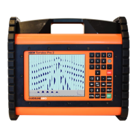
D. Using an external damping resistor:
- if a custom resistance value is desired it is possible to
mount one externally in parallel with the transmitter
loop;
- use a good quality “power resistor” that can withstand
the load put on it by the transmitter;
- the resistor should be attached to the instrument end
of the 3m TX lead-in cable (right) – although this image
depicts the connection on a WalkTEM 1, the
arrangement would look the same on a WalkTEM 2 TX
unit;
- connection of the Rogowski coil should be on the TX
lead-in cable and not around the resistor leads;
- the results of the Rogowski test for this external resistor
will be the decay labelled “none” as none of the internal
resistors are in use on that measurement.
NOTE: When a Rogowski coil test is run with an external resistor attached, the
decays shown for the internal resistors will be affected by the external resistor’s
presence; those decays will show the combined effect of the external resistor and the internal resistor.
E. Using an external damping resistor:
- the results of the tests are written out to a time-stamped folder and stored within the file structure of
the regular measurement data;
- the results are in a simple text format and therefore can be imported into other software packages for
plotting and / or further analysis.