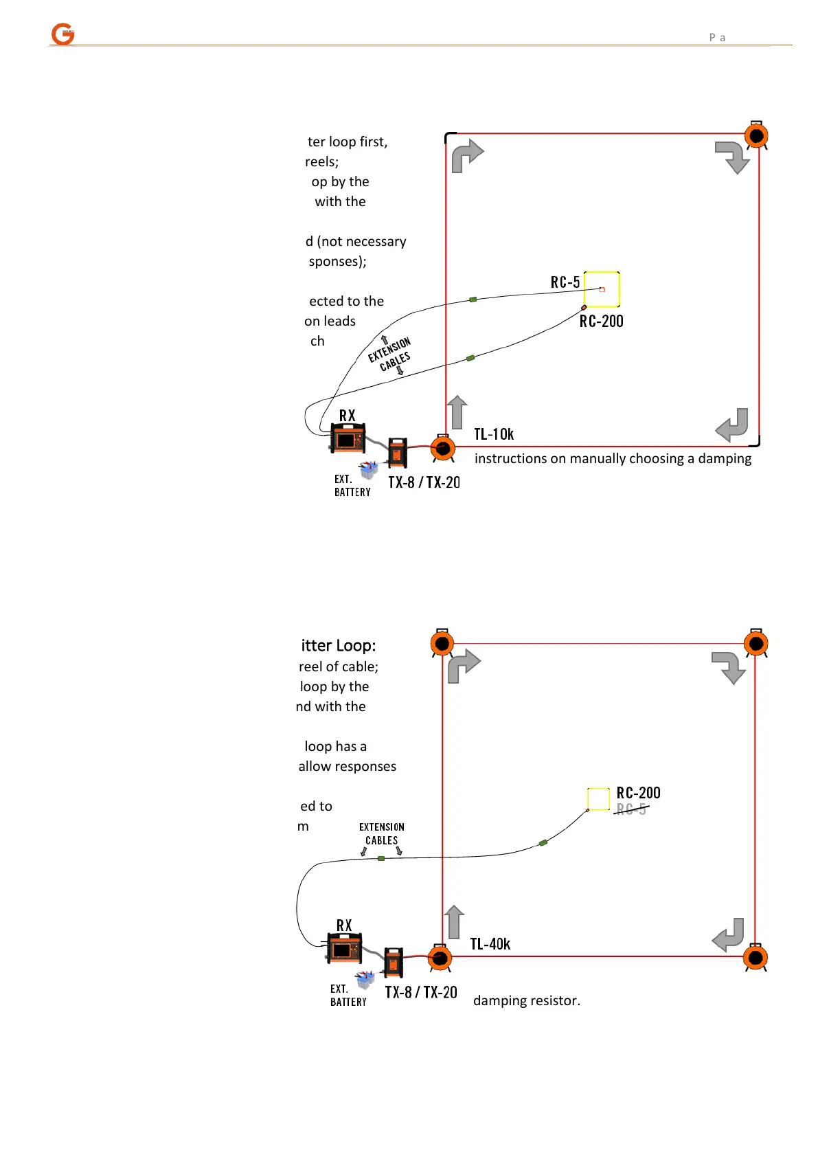
5. CENTRE LOOP LAYOUT (TL-10k HP6, 100x100m Transmitter Loop)
A. Similar layout to using the TL-1k6:
- pull out the TL-10k transmitter loop first,
this loop is split across two reels;
- leave the loose end of the loop by the
instrument and walk around with the
cable drums;
- next lay out the RC-5, if used (not necessary
if primary focus is deeper responses);
- lay out the RC-200;
- RC-5 / RC-200 are now connected to the
instrument via 62m extension leads
(total lead-in distance for each
coil is now 95m);
- the TL-10k is connected to
the TX unit via the 3m
lead-in cable;
- see Section 3 “Damping
Resistor Decisions” for instructions on manually choosing a damping
resistor.
B. Powering the TX:
- a 100m transmitter loop would normally be powered with a minimum of 24V (i.e. 2 batteries).
6. CENTRE LOOP LAYOUT (TL-40k HP6, 200x200m Transmitter Loop)
A. Start by laying out transmitter Loop:
- each side is one complete reel of cable;
- leave the loose end of the loop by the
instrument and walk around with the
cable drums;
- no RC-5 because the 200m loop has a
long switch-off time, so shallow responses
are undetectable;
- the RC-200 is now connected to
the instrument via two 62m
extension leads;
- the TL-40k is connected
to the instrument via
the 3m lead-in cable
again;
- see Section 3 “Damping
Resistor Decisions” for
instructions on manually
choosing a damping resistor.
B. Powering the TX:
- a 200m transmitter loop should be powered with a minimum of 24V (i.e. 2 batteries).