PROBOIL.2X user & installation guide v1e-2
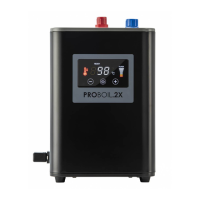
8. Check that the red 3/8” x 8mm boiler outlet connector (J) has
preinserted internally the 3/8” rubber seal (I), an additional
seal is supplied, ensure to use only 1 x 3/8” rubber seal in this
connection.
9. Screw the red 3/8” x 8mm boiler outlet connector (J) hand tight
(do not use a spanner or overtighten) on to the boiler 3/8”
male outlet (C).
10. Plug the power cable (D) securely into the socket on the left-
hand side of the boiler (A).
11. Hook the boiler keyhole slots onto its wall fixing screws (M) and check it is secure.
12. Take the ¼” blue flexible pipe (E) that caries the cold filtered
water output from the filter and rough out the minimum
amount of pipe needed to connect to the ¼” x ¼” pushfit
connector (F) found on the boiler inlet.
Mark the desired minimum pipe length with a permanent pen.
We recommend cutting the ¼” blue flexible pipe (E) at
least 200mm longer than the required minimum pipe length to
allow the boiler to be serviced more easily by your customer,
otherwise remove unnecessary/unneeded pipe length to keep
the installation tidy.
Cut the ¼” blue flexible pipe (E) to length cleanly and squarely
using a snip tool, sharp craft blade or similar.
13. Push the ¼” blue flexible pipe (E) fully and firmly into the ¼” x
¼” pushfit connector (F)
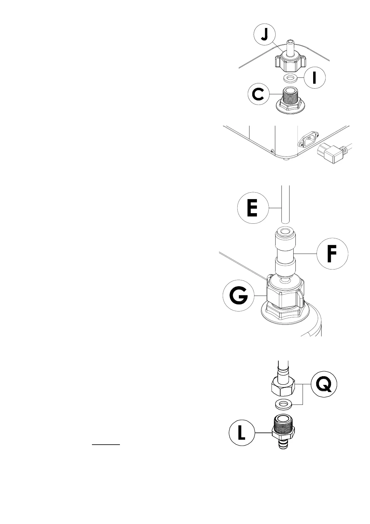
14. Firmly and fully push the silicone outlet tube (K) over the 8mm
barbed stem x 3/8” male tap connector (L).
15. Screw the 8mm barbed stem x 3/8” male tap connector (L) into
the 3/8” female flexible 110°C hose tap connector (Q), you
must ensure to use 3/8” the fibre seal (Q) (supplied separately
with the tap) is in this connection.
⚠ WARNING: You must not directly connect the tap hose
(Q) directly to the boiler output (C). You must always use
output adaptor (J) and silicone hose (K) to connect the tap.