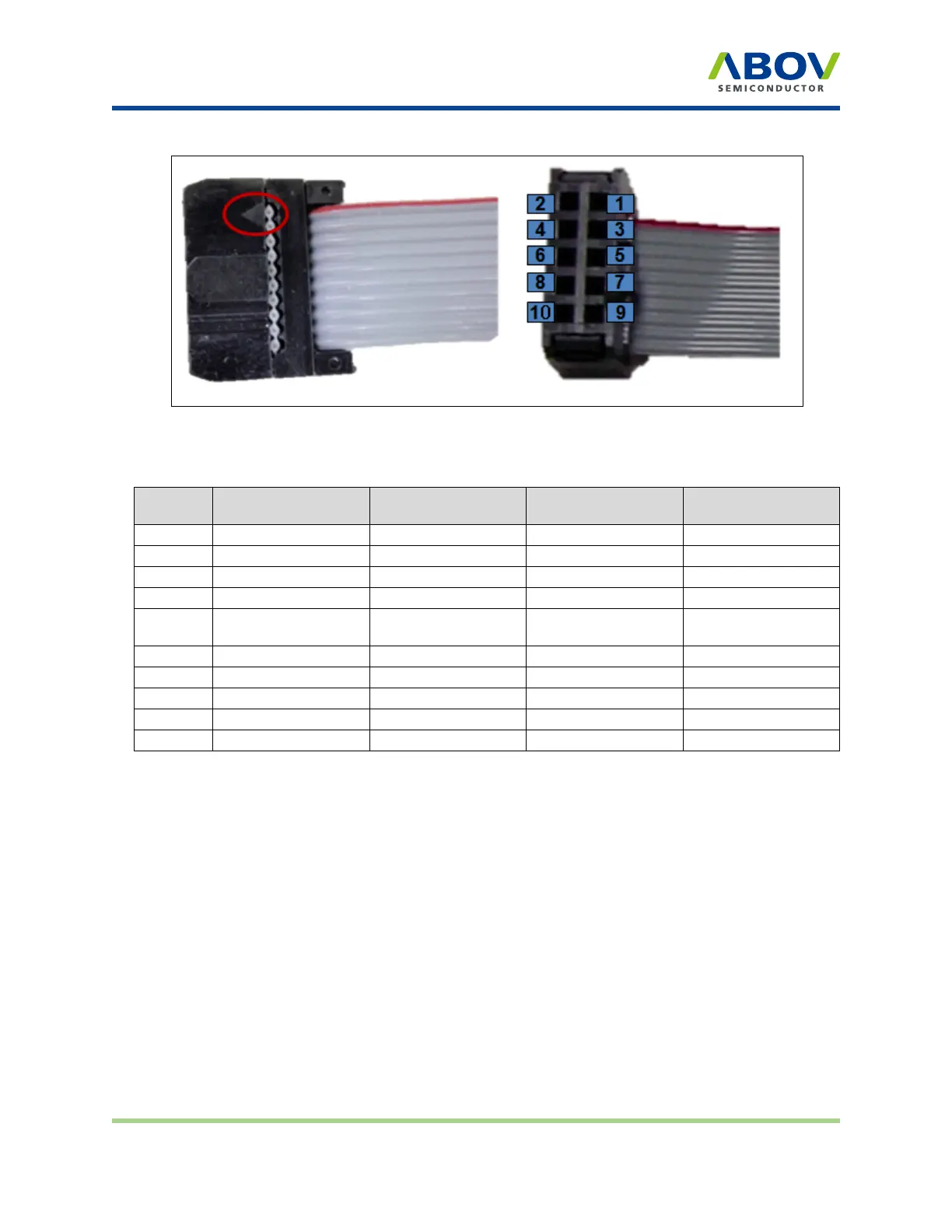
10-pin connector pin configuration
Figure 9: 10-pin IDC connector pin assignment
Table 3: 10-pin IDC connector pin configuration for each device group
Pin no.
Supported signals
AC33M6128/8128,
AC33M3064/4064
MC80F7708 UART
ISP
32-bit SWD
1
MCU UART-RX MCU UART-RX MCU UART-RX
N/A
2
VDD VDD VDD VDD
3
MCU UART-TX MCU UART-TX MCU UART-TX
N/A
4
GND GND GND GND
5
Run Flag or Boot
Pin or ACK
Boot Pin
ACK
N/A
6
Clock
N/A N/A
SWD-CLK
7
GND
N/A N/A N/A
8
Data
N/A N/A
SWD-DATA
9
N/A N/A N/A N/A
10
VPP or Reset Pin
RESET VPP RESET
E-PGM+ E-GANG4/E-GANG6 E-PGM Serial Page 14 / 33 Version 1.0.0