36 37
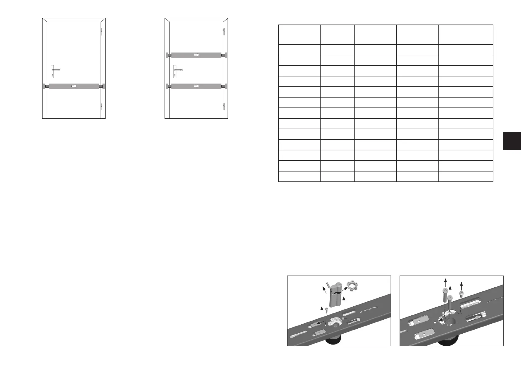
Fig. 3 Fig. 4
GB
PR2600
PR2600
PR2600
IV. Fitting tools
• Screwdrivers
• Drilling machine
• Metal drill: Ø 3,0 mm
(also use with wood) Ø 3,5 mm
Ø 5,0 mm
Ø 8,5 mm
Ø 10,0 mm
• Masonry drill bit: Ø 10,0 mm, length of at least 160 mm, as good as new
Ø 6,0 mm
Ø 16,0 mm, for a wall lock
• Milling cutter/hole saw: Ø 51 - 55 mm
• Mechanic‘s level, metering rule
• Metal saw, file
• Tools for additional work are not included in this installation
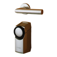
V. Replacing the door cylinder (optional)
If the door cylinder does not need to be replaced, continue to read under chapter VI.
With door leaf strengths above 50 mm and/or if the door cylinder has to fit in a locking
system, the standard door cylinder must be replaced.
The same applies if it is set to be fitted without any option to lock from outside.
1. New door cylinder correspond to DIN EN 1303/DIN 18252 and obtain spacers and longer screws if
required:
• With door leaf strengths greater than 50 mm: Obtain door cylinder of a greater length
(see table 1), as well as spacers and longer screws if required
• Use the door half-cylinder 10/30 when fitting without the possibility of opening / closing
from the outside
Table 1
Door panel
thickness in mm
Cylinder
dimensions
Spacer disc DS05
PR 5 mm (Item
no. 24363)
Spacer disc DS10
PR 10 mm (Item
no. 4623)
Screws
DIN 7984-8.8. in mm
35 - 50 30/60 - - M6 x 45 (enclosed)
51 - 55 30/65 1 - M6 x 45 (enclosed)
56 - 60 30/70 - 1 M6 x 45 (enclosed)
61 - 65 30/75 1 1 M6 x 45 (enclosed)
66 - 70 30/80 - 2 M6 x 45 (enclosed)
71 - 75 30/85 1 2 M6 x 60 (Item no 1685)
76 - 80 30/90 - 3 M6 x 60 (Item no 1685)
81 - 85 30/95 1 3 M6 x 60 (Item no 1685)
86 - 90 30/100 - 4 M6 x 60 (Item no 1685)
91 - 95 30/105 1 4 M6 x 80 (Item no 1686)
96 - 100 30/110 - 5 M6 x 80 (Item no 1686)
101 - 105 30/115 1 5 M6 x 80 (Item no 1686)
106 - 110 30/120 - 6 M6 x 80 (Item no 1686)
2. Lock door bars and remove the door cylinder in the specified order according to Fig. 5.
3. Change the grub screw and the gear-wheels clip of the standard door cylinder to the new door
cylinder, according to Fig. 5. The grub screw must protrude at the same distance on both sides.
If the cylinder length does not change, continue to point 8.
4. Unscrew the loosened screw 1 (Fig. 6), move the gear-wheel housing in the direction of the
arrow. Unscrew the cylinder protection‘s screws located beneath (Fig. 6).
5. Remove the cylinder protection according to Fig. 7 and place additional spacer disc/s (Tab. 1.)
between the cylinder protection and the lock body. Tighten with screws (Tab. 1).
6. Pull the gear-wheel housing into the old fitting position again (Fig. 6) and fix loosely with
screw 1.
7. Push toothed gear racks in the direction of the arrow (fig. 8) until they stop, whereby the
upper ones must be pushed back by one tooth.
2.
3.
1.
3.
Fig. 6Fig. 5
3.
5.
6.
4.
2.
1
.
loosen