26
RP
M Pulses / Crank Revolution
This table is used to accurately calculate Engine Speed from the signal seen on the
Engine Speed input. Enter the number of trigger events on the Engine Speed input
that equates to 1 revolution of the engine.
Driveshaft Pulses / Revolution
This table is used to accurately calculate Vehicle Speed in Miles Per Hour from the
signal seen on the Output Shaft Speed input. Enter the number of trigger events on
the Output Shaft Speed input that equates to 1 revolution of the engine driveshaft.
Tire Diameter
This table is used in calculating Vehicle Speed. Enter the actual measured diameter
of your tire in Inches.
Rear Gear Ratio
This table is used in calculating Vehicle Speed. Enter the exact input/output gear
ratio used in your vehicle.
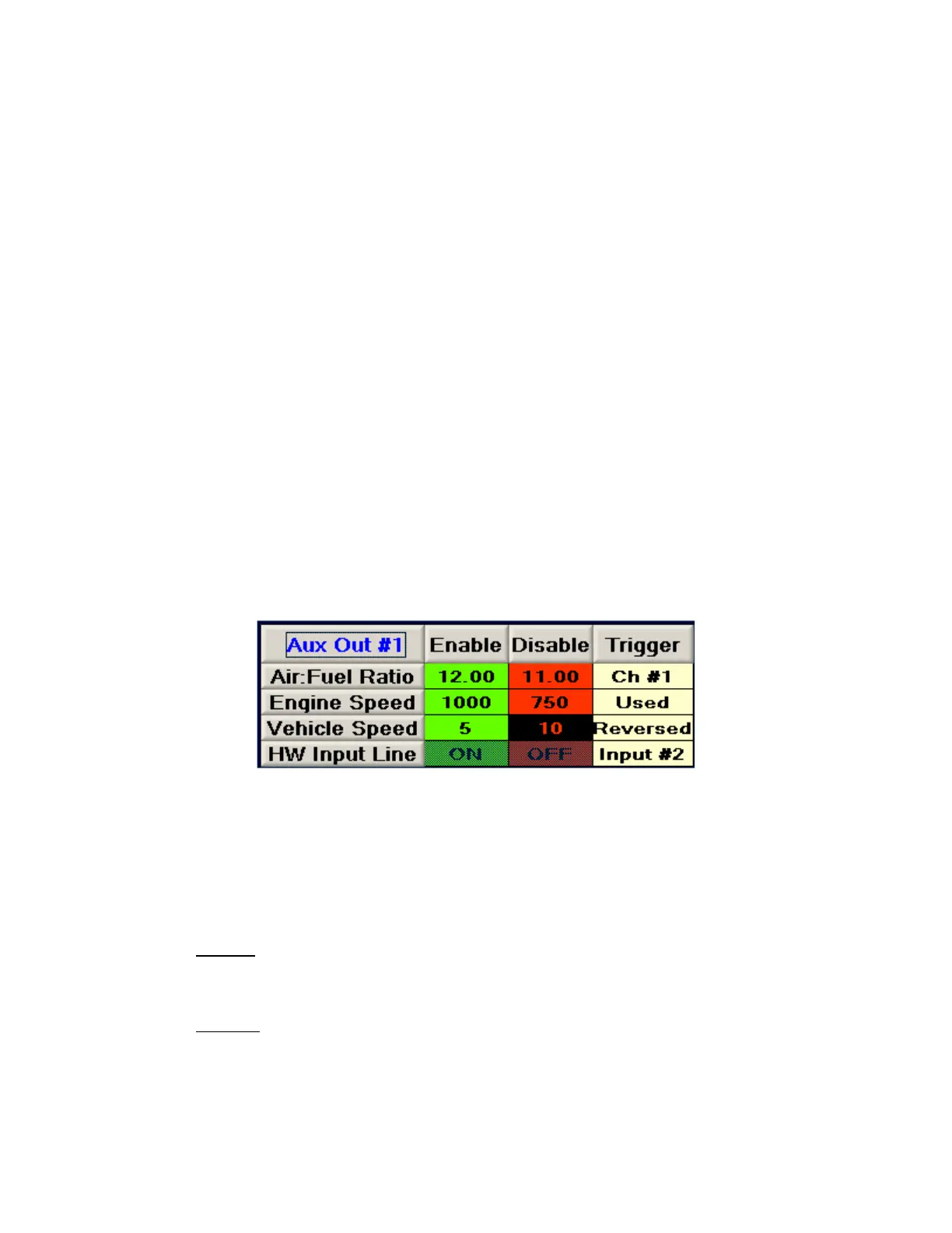
Auxiliary Output Configuration
Each auxiliary output can be configured to operate based on current Air:Fuel ratio,
Engine Speed, and Vehicle Speed value(s), along with an optional hardware enable
input. Single Channel models have 2 available outputs, and Dual Channel models
have 4 available outputs. These outputs provide a ground signal designed to trigger
a relay or signal a low-current input on an external device.
To
change a value in any output triggering table, click on the data value you want to
change. Enter a new value in its place and press the ENTER key to send the change
to the Engine Analyzer Module. For the trigger column, repeatedly pressing the
ENTER key will cycle through the list of possible choices for the triggering logic
values.
The outputs respond to their respective triggering parameters in the following ways:
Enable:
The data value must rise above (or drop below) the ENABLE
va
lue to allow the output to be activated, depending upon the
trigger logic setting.
Disable:
Once the ENABLE condition has been satisfied, the data value
mu
st normally remain above (or remain below) the DISABLE
value in order to keep the output activated, depending on the
trigger logic setting.