www.accuenergy.com
V: 1.0 Revised: Jan. 2018
13
Chapter 2: Installation - Physical Setup
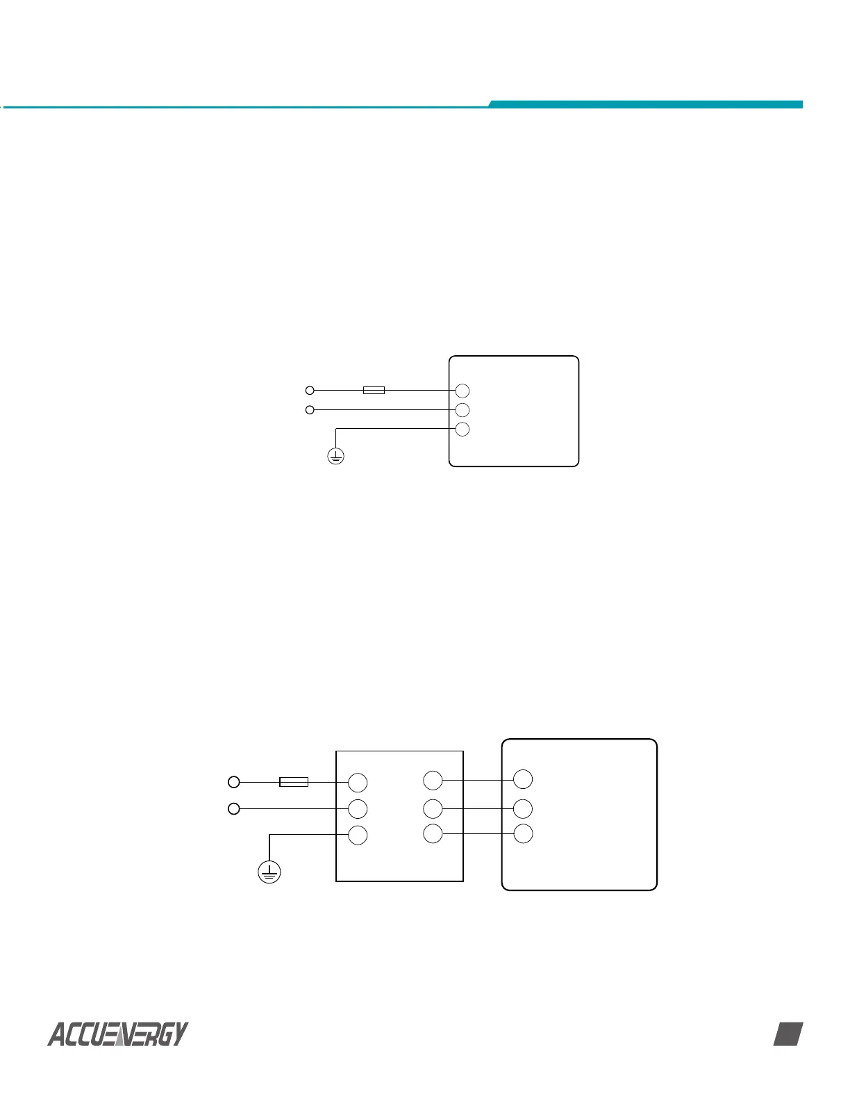
1A FUSE
Power Supply
EMC lter
AcuDC 240
11
12
13
L/+
N/-
G
L
N
G
L
N
G
2.3.1 Wiring Control Power
CAUTION: Make sure you check the power supply option you have before energizing the
meter. Check the silver sticker on the side of the meter to confirm what power supply
option you have.
The silver sticker on the side of the meter contains information such as the model
number, power supply, voltage/current inputs and serial number.
To power the meter, you need to connect the power supply terminal as shown below.
This will be connected based on the two power supply options available, that is:
1A FUSE
Power Supply
AcuDC 240
11
12
13
L/+
N/-
G
Fig 2-9 Power Supply Wiring
2-10 Power Supply Wiring with EMC Filter
Choice of wire power supply is AWG16-22 or 0.6-1.5 mm
2
.
1. The Standard option: 100-240Vac, 50/60Hz or 100-300Vdc
2. The Low Voltage DC option: 20-60Vdc
The independent power supply circuit loop must have a fuse or air circuit breaker. The
fuse could be 1A/250Vac, time delay type. If circuit breaker is used, a CE certified product
with compliance of IEC947 is recommended.
Terminal G (13) must be connected to the ground for the safety.
An isolated transformer or EMC filter should be used in the auxiliary power supply loop if
power quality problem exists in the power supply, as shown in following figure.

 Loading...


