Page 24Page 23
Sky Tech TS6i
+
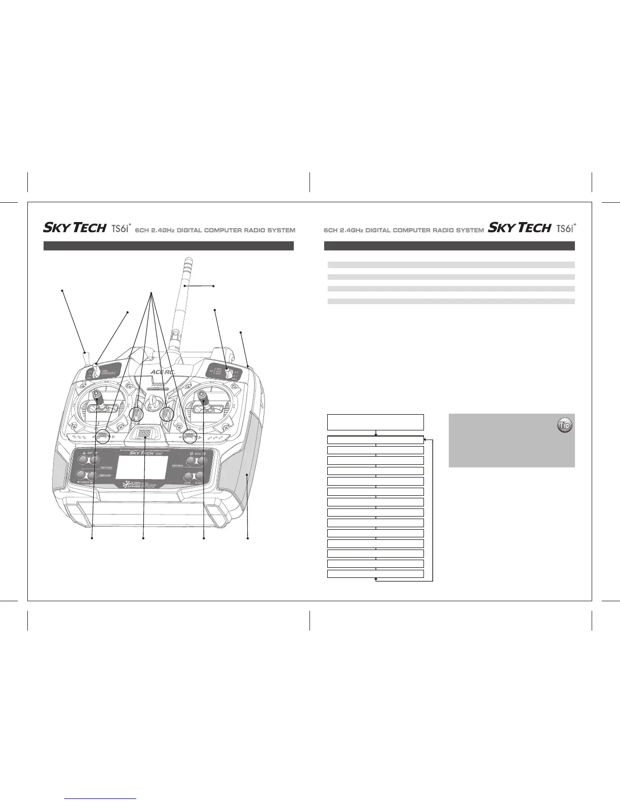
ACRO in-Flight Controls Model Setup Menu Programming for Powered Airplanes (ACRO)
This figure shows the assignments for a Mode 2 system as supplied by the factory.
Note that some of the functions will not operate until activated in the mixing menus.
To set up the Sky Tech TS6i
+
to fly a particular model, you need to get into the radio's second programming menu: the model setup menu. In
this menu you can program specific control functions; set servo throw direction; and set the values of servo travel, exponential rates and dual
rates for the particular model you selected earlier in the initial setup menu.
Go ahead and switch the transmitter on-you are now in the standard operating screen.
In the upper left-hand corner it will say "ACRO" and to the right there will be a large number telling you the state of the battery voltage (such
as 7.2 v) and a smaller single-digit number indicating the model slot the radio is currently opened to.
There will also be a little black box at the bottom of the screen with the symbol "NOR". This indicates that the system is currently in the
"normal" flight condition mode. Later, we will show you how to activate the flight condition modes-and it is here on the screen where you will
be told which mode is currently active.
Now push down both EDIT buttons at the same time. The following menu items will appear as you scroll down the list by pushing down the
right-hand EDIT button:
Trainer/Engine Cut Switch
SW 3
SW 1
Rudder &
Throttle Stick
Aileron &
Elevator Stick
Plastic Side Panel
SW 2
Antenna
Trim Switch
Power Switch
ACRO Functions Map
EPA End Point Adjust (Servo travel) 25 D/R Dual Rates 27
EXP Exponential Settings 28 S-TRM Sub-Trim (Neutral Settings) 29
S-REV SERVO Reverse 29 P.MIX Programmable Mixer 30
31
ELVN Elevon Mixing (Tailless models) 31 FLPN Flaperon (Combined Flaps & Ailerons)
V-TAL V-tail Mixing 32 A->R Rudder Coupling 33
E->F Elevator Flap Mixing 33 CUT Throttle Cut (Engine Shut Off) 34
35
CAMB Camber (Combined Flaps & Ailerons) 34 FLT.C Flight Condition (NOR, ST1, ST2, ST3)
Voltage/Timer Display
Normal Display Mode
End Point Adjust [EPA]
Press both Edit buttons
Dual Rate Set [D/R]
Exponential [EXP]
Sub -Trims [S.TRM]
Servo Reversing [REV]
Programmable mix [PMIX]
Elevon Mix [ELVN]
Flaperon Mix [FLPN]
V-Tail [VTAL]
Ail->Rud Mix [A-R]
Elev->Flap Mix [E-F]
Throttle Cut [T.CUT]
Camber [CAMB]
FLT.C
When programming a model for the first time,
start with setting servo direction and then
activate any mix's needed like Flaperon, Elevon
or Aileron/Rudder.
Next, progress through adjusting subtrim and
setting end point travel of each servo; then set
exponential and dual rate values.
Gear Swich (SW-1) Controls - Receiver CH5
FLT MODE (SW-3) Switch Aft = CAMB On