8 Blue video GND
3. FUNCTION CHECK
3.1 OSD Function Test
3.1.1 Test mode: 1440x900 @ 60 Hz
3.1.2 Test pattern: pattern #1 of crosshatch (GENERAL-1)
3.1.3 Check single key function and hot key function about key “Power”, “Menu”,” ►”, “◄ “,
“Exit/Auto”, it should operate normally
3.2 Screen Picture Check
3.2.1 Test mode: 1440x900 @ 60 Hz
3.2.2 Test pattern: pattern #1 of crosshatch (GENERAL-1)
3.2.3 Select OSD menu to execute ‘Auto’ function, screen picture shouldn’t appear abnormal
phenomenon and picture on screen should fit in with active display screen.
3.3 Auto Color Balance
3.3.1 Test mode: 640x480 @ 60 Hz
3.3.2 Test pattern: pattern #42 of 5-MOSAIC
3.3.3 Enter "Factory Mode" pressing "Auto color" key, and execute "AUTO".
3.4 Timing Check
3.4.1 Test mode: Refer to preset timing table and power saving mode
3.4.2 Test pattern: pattern #1 of crosshatch (GENERAL-1)
3.4.3 After change above timing and execute “Auto” function automatically, picture should fit in with
active display screen.
3.4.4 Under power saving mode, LED lamp on the key board should be orange
3.5 Power Consumption Function Test
3.5.1 Test mode: 1440x900 @ 60 Hz
3.5.2 Test pattern: pattern #11 of “BLACK”
3.5.3 Adjusting both brightness and contrast value to maximum,
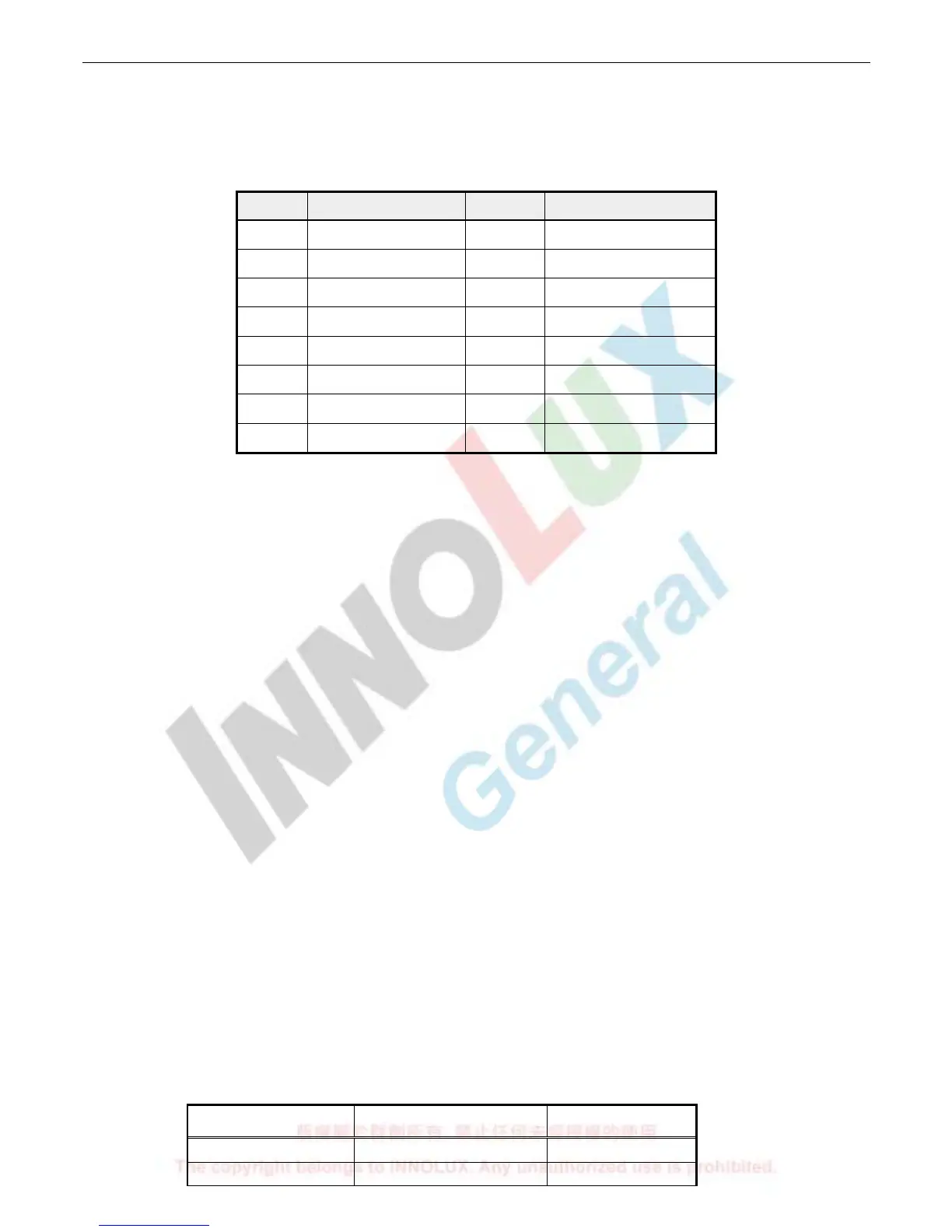
3.5.4 Measure power consumption as the following
Status Power Consumption LED Display
Normal < 42W(with audio) Green
Standby (No H/V < 1W Amber

 Loading...