Do you have a question about the Acer Aspire 1300 and is the answer not in the manual?
Lists key features like processor, memory, display, multimedia, and connectivity options.
Illustrates the internal components and their interconnections within the system.
Shows the physical arrangement of components on the motherboard's top side.
Depicts the component layout on the motherboard's bottom side.
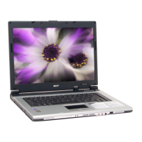
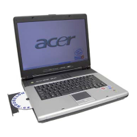
Provides an overview of the laptop's external front view and its ports.
Details the ports and components located on the left side of the laptop.
Describes the ports and components situated on the right side of the laptop.
Identifies ports and features on the back of the laptop.
Shows components and access points on the underside of the laptop.
Explains the status indicators for power, battery, and drive activity.
Covers keyboard layout, special keys, and embedded keypad functionality.
Details the touchpad operation, basic functions, and click/scroll actions.
Describes the function of dedicated keyboard keys for launching applications.
Lists detailed specifications for processor, BIOS, memory, and interfaces.
Guide to accessing and navigating the BIOS Setup Utility for system configuration.
Instructions for updating the system's BIOS flash memory.
Information on creating and using a diagnostic diskette for system testing.
Essential safety precautions and steps before disassembling the computer.
Visual guide outlining the sequence for disassembling system components.
Step-by-step instructions for removing memory and hard disk drive modules.
Procedures for disassembling the keyboard and LCD assembly.
Detailed steps for taking apart the main internal components of the laptop.
Instructions specifically for disassembling the 14.1-inch LCD module.
Instructions for disassembling the 15.1-inch LCD module.
Procedures for removing external components like HDD, FDD, and optical drives.
Steps for diagnosing issues with diskette, CD-ROM, keyboard, and memory.
Steps to troubleshoot keyboard and other input devices.
Procedure for checking memory errors and ensuring proper DIMM installation.
Steps to diagnose power-related issues using battery and AC adapter.
Troubleshooting steps for a non-functional touchpad.
Guide to interpreting and resolving POST error messages.
A list of common error messages and their corresponding FRU actions.
Maps symptoms to potential FRU replacements for LCD, indicators, and power issues.
Strategies for diagnosing and resolving intermittent system hangs and issues.
Procedures for isolating failing FRUs when problems are not clearly identified.
Identifies jumpers and connectors on the top side of the motherboard.
Locates jumpers and connectors on the bottom side of the motherboard.
Visual representation of system components for identification and repair.
Diagram showing the parts of the Floppy Disk Drive assembly.
Table defining different Aspire 1300 models with CPU, LCD, ODD, HDD, and battery specs.
Summarizes the key performance and system features of the Aspire 1300 series.
Lists components and peripherals tested and verified under Windows XP Home.
| Display | 1024x768 resolution |
|---|---|
| Graphics | ATI Radeon IGP 320M |
| Optical Drive | DVD/CD-RW combo drive |
| Battery | Lithium Ion |
| Ports | 3 x USB 2.0, VGA |
| Wireless | 802.11b |
| Operating System | Windows XP Home |
| Weight | 2.8 kg (6.17 lbs) |


