
K
Katrina AllenAug 29, 2025
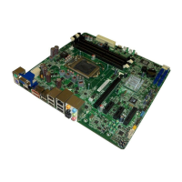
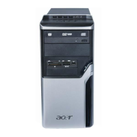
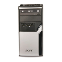
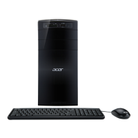
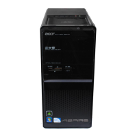
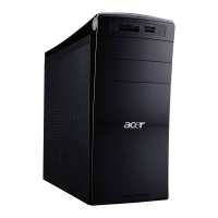
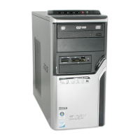
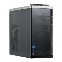
How to fix '5th Master Hard Disk Error' on Acer Aspire M5811 Desktop?
- AAlex WeaverAug 29, 2025
The IDE/ATAPI device configured as Master in the 5th IDE controller could not be properly initialized by the BIOS. Check the connection and configuration of the device.