Do you have a question about the Acer Aspire SA85 and is the answer not in the manual?
Provides a general description of the system's integrated components and their capabilities.
Details the processor, chipset, PCB, memory, graphics, PCI, FDD, IDE, Audio, LAN, IEEE 1394, USB, and BIOS specifications.
Illustrates the physical layout of components on the motherboard with labeled parts.
Presents a visual representation of the system's architecture and component interconnections.
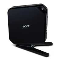
Details the components and ports located on the front panel of the Aspire SA85 computer.
Identifies and describes the ports and connectors on the rear panel of the Aspire SA85 computer.
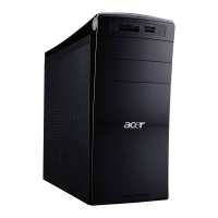
Details the components and ports located on the front panel of the AcerPower S285 computer.
Identifies and describes the ports and connectors on the rear panel of the AcerPower S285 computer.
Describes basic system peripherals like mouse and keyboard, including connection types.
Explains the Acer eRecovery utility for system backup, restore, and software re-installation.
Details the process for restoring the system drive without a recovery CD and multilingual OS installation.
Provides instructions on how to enter the BIOS Setup Utility using the DEL key during POST.
Displays system product name, serial number, BIOS version, and SMBIOS version.
Allows configuration of basic system parameters like date, time, and IDE devices.
Covers settings for silent boot, CPU features, boot order, security, and video BIOS.
Allows modification of chipset registers for system options, including DRAM and AGP settings.
Enables configuration of onboard devices like IDE, PCI, LAN, and Super IO devices.
Configures system power saving modes, suspend types, HDD power down, and wake-up events.
Manages Plug and Play configurations, IRQ resources, and PCI/VGA palette snooping.
Displays system voltages, CPU temperature, ambient temperature, and fan speeds.
Allows adjustment of CPU speed, DIMM/PCI clock detection, and spread spectrum settings.
Provides an option to load default BIOS settings for the system.
Enables setting or disabling Supervisor and User passwords for BIOS access.
Saves current BIOS settings to CMOS and exits the Setup Utility.
Discards any changes made in the Setup Utility and exits without saving.
Outlines necessary precautions before starting the disassembly procedure, like unplugging power.
Provides step-by-step instructions for opening the system and removing the front panel and cables.
Explains how to set motherboard jumpers for system configuration, including SHORT and OPEN states.
Details pinouts and signal names for ATX power, CPU fan, SYS fan, and front panel connectors.
Provides a visual exploded view of the computer system with numbered parts and their descriptions.
Lists computer components, their part names, descriptions, and Part Numbers (P/N).