40
Color temperature Standard/Warm/Cold (x, y) co-ordinates specification:
Table: Reading with Minolta CA-110.
Note:
1. Use Minolta CA-110 for color coordinates and luminance check.
2. Luminance > 400 cd/m
2
in the center of the screen when Brightness control at 100; Contrast control at 100
3. Reset AV setting, smart picture shall be recalled to be “Standard” and Contrast= (TBD) (CMO),
Brightness=(TBD) (CMO)
PC mode display adjustment
WHITE-D adjustment (B)
General set-up:
Equipment Requirements: Minolta CA-110 or Equivalent Color analyzer
Chroma 2250 or equivalent PC signal generator
Input requirements:
Input Signal Type: PC VGA signal
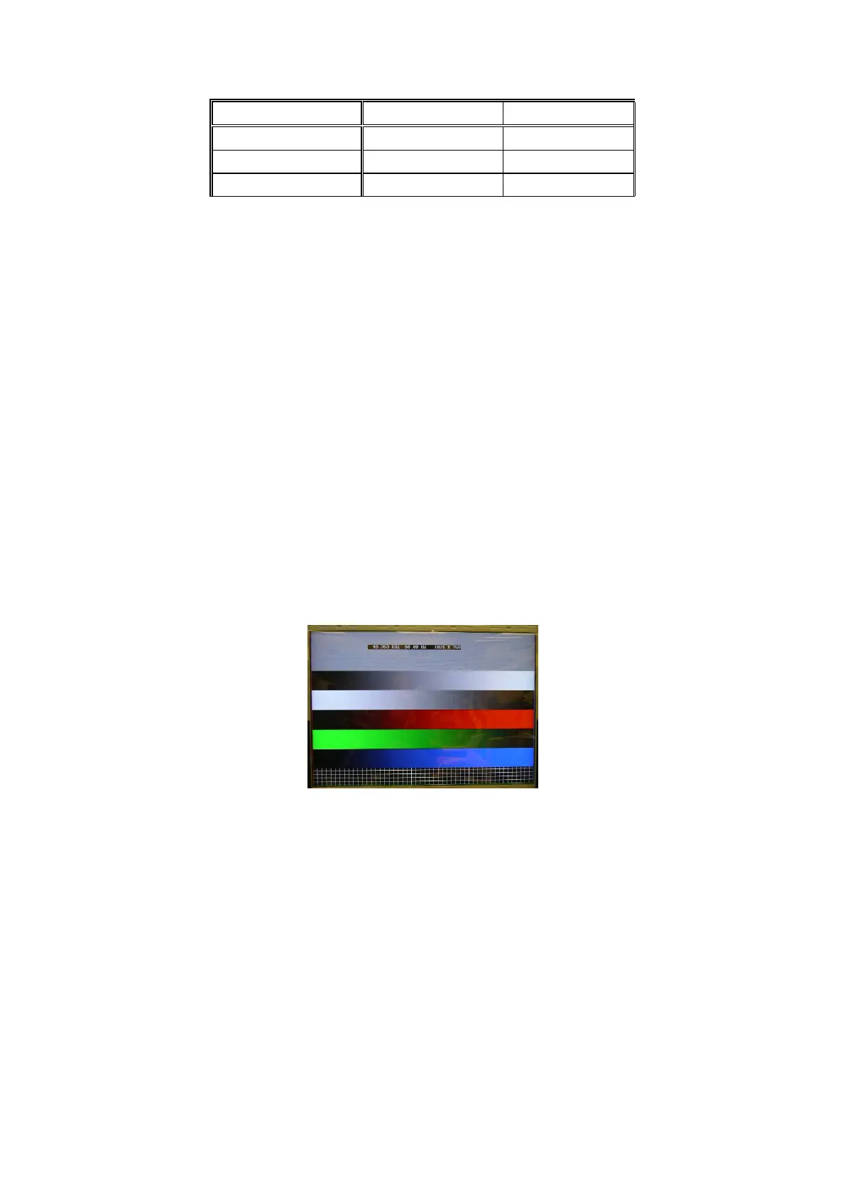
1024X768/60Hz PC mode with PGCWRGB pattern. (see pattern-1)
Input Signal Strength: 0.7 Vp-p linear voltage.
Input Injection Point: PC D-SUB input
Pattern-1
Alignment method:
Initial Set-up:
1. Select source as “VGA”.
2. Set Contrast = 50 (CMO) and Brightness=50 (CMO), at Standard menu mode.
3. Apply “PGCWRGB”(pattern-1) pattern by VGA pattern generator.
4. Enter factory mode menu: press “MENU+ “234” then enter FAC mode
Alignment:
1. At FAC mode menu, select FACTORY->Picture ->ADC -> Auto Colour item. Then press “>” key to adjust
ADC_GAIN_R, ADC_GAIN_G, ADC_GAIN_B and ADC_OFFSET_R, ADC_OFFSET_G, ADC_OFFSET_B. Then
store those values to NVM.
Picture Mode x Y
Normal (10000
o
K) 0.281±0.005 0.288±0.005
Warm (8000
o
K) 0.295±0.005 0.305±0.005
Cold (13000
o
K) 0.269±0.005 0.274±0.005
 Loading...