1-18 Disassembly Procedures
Mainboard Removal 0
Prerequisite:
WLAN (Wireless Local Area Network) Module Removal and
LCD Module Removal
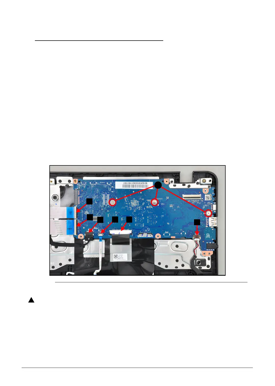
1. Locate the mainboard (B) on the top assembly. Refer to Figure 1-9.
2. [For C733T & C733 only] Disconnect the 30-pin USB board FFC from the mainboard
connector (C) (Figure 1-23).
3. Disconnect the 40-pin USB board FFC from the mainboard connector (D)
(Figure 1-23).
4. [For C733T & C733 only] Disconnect the USB board power cable from the mainboard
connector (E) (Figure 1-23).
5. Disconnect the touchpad FFC from the mainboard connector (F) (Figure 1-23).
6. Disconnect the keyboard FPC from the mainboard connector (G) (Figure 1-23).
7. Disconnect the speaker cable from the mainboard connector (H) (Figure 1-23).
8. Remove three (3) screws (A) securing the mainboard in place (Figure 1-23).
Figure 1-23. Mainboard Connector & Screw Location
Make sure all FFCs, FPCs and cables are disconnected from the mainboard
connectors to avoid damage during the removal process.
 Loading...