7
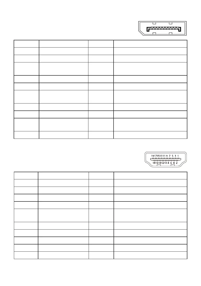
Connector pin assignment
20-pin color display signal cable*
Threading Explanations Threading Explanations
1. Channel 0 real signal 11. Monitor ground
2. Monitor ground 12. Channel 3 auxiliary signal
3.
Channel 0 auxiliary
signal
13. Reserved (protocol pull)
4. Channel 1 real signal 14. Reserved (protocol pull)
5. Monitor ground 15. Auxiliary channel real signal
6.
Channel 1 auxiliary
signal
16. Signal detection
7. Channel 2 real signal 17. Auxiliary channel auxiliary signal
8. Monitor ground 18. Hot plug detection
9.
Channel 2 auxiliary
signal
19. Monitor ground
10. Channel 3 real signal 20. 3.3 V power supply
* Limited to specic models
19-pin color display signal cable*
Threading Use Threading Use
1. TMDS data 2 + 10. TMDS clock +
2. TMDS data 2 mask 11. TMDS clock mask
3. TMDS data 2 - 12. TMDS clock -
4. TMDS data 1 + 13. CEC
5. TMDS data 1 mask 14.
Reserved
(not connected on the device)
6. TMDS data 1 - 15. SCL
7. TMDS data 0 + 16. SDA
8. TMDS data 0 mask 17. DDC/CEC ground
9. TMDS data 0 - 18. +5 V power supply
19. Hot plug detection
* Limited to specic models
13579
1113151 719
246810
1214161 820

 Loading...