Do you have a question about the Acer TravelMate B113-M and is the answer not in the manual?
Detailed specifications and configurations for the laptop hardware.
Summary of the computer's various features.
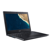
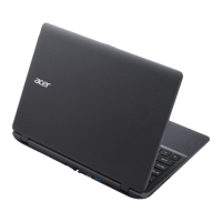
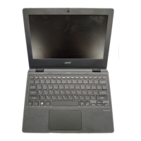
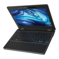
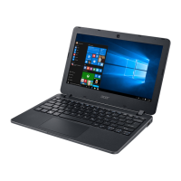
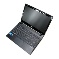
Visual guide to the laptop's external components and layout.
Description of ports and indicators on the laptop's front side.
Identifies ports and vents located on the left side of the laptop.
Details ports and the security lock slot on the laptop's right side.
Illustrates components visible on the bottom of the laptop.
Explanation of touchpad functionality and operations.
Overview of keyboard keys and their functions.
Diagram showing the interconnections of system components.
Comprehensive table of the laptop's technical specifications.
Tools and utilities for system management and configuration.
Program to configure hardware settings and boot options.
Guide on how to use the BIOS interface and its menus.
Displays detailed hardware information of the computer.
BIOS settings for system time, date, and boot options.
Options for setting supervisor, user, and HDD passwords.
Configuration of boot device order and related settings.
Options for saving or discarding BIOS changes and exiting the utility.
Procedures for updating the system BIOS.
Instructions for updating BIOS using DOS environment.
Instructions for updating BIOS using the Windows environment.
Utilities for managing system information and passwords.
Details on unlocking HDD and managing BIOS passwords.
Steps to remove BIOS password checks.
Standard Operating Procedures for BIOS recovery.
Guide to preparing a USB drive for BIOS recovery.
Steps for performing BIOS recovery using a crisis disk.
Identification of connectors on the top side of the mainboard.
Identification of connectors on the bottom side of the mainboard.
Layout of LEDs and connectors on the LED board.
Layout of ports and connectors on the IO board.
Layout of connectors on the HDD board.
Location and function of the Clear CMOS jumper.
General procedures and guidance for troubleshooting computer issues.
Steps to diagnose and resolve problems with the system not powering on.
Troubleshooting steps for when the system does not display video.
Procedures for diagnosing and fixing LCD screen display problems.
Steps to troubleshoot issues with the built-in keyboard.
Troubleshooting guide for touchpad malfunctions.
Steps to resolve problems with the internal speakers.
Troubleshooting guide for internal microphone issues.
Steps to diagnose and fix USB port connectivity problems.
Troubleshooting steps for wireless and Bluetooth failures.
Troubleshooting steps for the 2-in-1 card reader function.
Diagnosing and resolving issues related to unit overheating.
Troubleshooting for physical appearance issues with the laptop.
Troubleshooting for other non-specific hardware functions.
Common issues related to BIOS settings and operations.
Guidance for diagnosing and resolving sporadic system issues.
Procedures for isolating faults when the cause is unclear.
Overview of the chapter's content on maintenance and repair.
List of tools required for notebook maintenance.
Diagram illustrating component removal and installation sequences.
Prerequisites and initial steps before performing maintenance.
Step-by-step guides for removing and installing the laptop battery pack.
Procedures for removing and installing the dummy card from the SD card slot.
Instructions for removing and reinstalling the bottom access panel.
Step-by-step guides for removing and installing the Hard Disk Drive module.
Procedures for removing and installing RAM modules (DIMMs).
Steps to remove and install the Wireless LAN module.
Instructions for removing and reinstalling the top cover assembly.
Procedure for removing and installing the main logic board.
Steps to remove and install the Input/Output board.
Procedure for removing and installing the LED indicator board.
Steps to remove and install the laptop's internal speakers.
Procedure for removing and installing the laptop keyboard.
Procedure for removing and installing the touchpad module.
Steps to remove and install the CPU thermal module and fan.
Procedure for removing and installing the entire LCD assembly.
Steps to remove and install the frame around the LCD screen.
Procedure for removing and installing the LCD screen panel.
Procedure for removing and installing the camera module.
Procedure for removing and installing the LCD panel mounting brackets.
Steps to remove and install the internal microphone components.
Procedure for removing and installing the primary WLAN antenna cable.
Procedure for removing and installing the auxiliary WLAN antenna cable.
List of parts that can be replaced by the user or technician.
Visual breakdown of assemblies with numbered parts.
Exploded view and parts list for the main laptop assembly.
Exploded view and parts list for the lower case components.
Exploded view and parts list for the upper case components.
Exploded view and parts list for the LCD screen assembly.
Exploded view and parts list for the Hard Disk Drive assembly.
Detailed list of all Field Replaceable Units with part numbers.
List of screws used in the laptop, with specifications.
Lists components verified for compatibility with the system.
Compatibility test results under Windows 7 environment.
Information on accessing online technical support and resources.
Overview of available online support services and resources.
| Resolution | 1366 x 768 |
|---|---|
| Operating System | Windows 8 Pro |
| Battery Life | Up to 5 hours |
| Graphics | Intel HD Graphics |
| Battery | 4-cell Li-ion |
| Processor | Intel Celeron |
| Display | 11.6 inches |
| RAM | DDR3 |
| Storage | 500 GB HDD |