Do you have a question about the Acer Veriton X4610G and is the answer not in the manual?
Brief summary of the computer's many features, for reference only.
Details on the CPU socket type, quantity, and processor type.
Information about the Intel Q65 chipset and its design criteria.
Specifications for the Printed Circuit Board (PCB) size and form factor.
Details on memory socket type, quantity, capacity, and dual channel support.
Specifications for SATA interface, drive sizes, and RPM.
Details on SATA interface and supported ODD types.
Information on Intel HD Graphics support, display outputs, and technologies.
Mechanical restrictions for installing graphics cards.
Details on SATA connector type, quantity, and storage support.
Specifications for the Intel 82579LM Gigabit LAN controller.
Details on the HD audio codec, connectors, and support.
Information on USB controller, port quantity, and data transfer rates.
Details on PCI Express x16 and x1 slots.
Indicates the presence of an on-board buzzer.
List of connectors available on the rear panel of the system.
Details of connectors located directly on the motherboard.
Information about the AMI Aptio Kernel BIOS and its type.
Requirements for power supply rating, protection circuits, and certification.
Visual representation of the system's components and their connections.
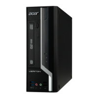
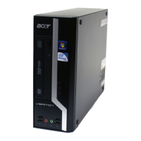
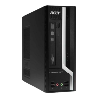
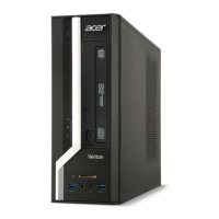
Overview of the system's interior and exterior components.
Identification and description of components on the front panel.
Identification and description of components on the rear panel.
Detailed specifications for processor, BIOS, and major motherboard chips.
Table showing supported memory configurations for each slot.
Detailed specifications for system memory type, voltage, and package.
Details on audio controller, channel, function, and sampling rate.
Specifications for the SATA controller, channel number, and support mode.
Details on universal HCI, USB class, and connector quantity.
Operating and non-operating temperature, humidity, and vibration specs.
Table showing power management states (S1-S5) for various devices.
Details on Device Standby, Global Standby, and Suspend modes.
Introduction to the CMOS Setup Utility for hardware configuration.
Step-by-step guide on how to access the CMOS setup.
Explanation of keys used for navigating within the BIOS setup utility.
Description of the main setup categories and parameters in BIOS.
Overview of advanced BIOS settings categories like Miscellaneous and Chipset.
Details on miscellaneous BIOS settings like AHCI ports and spread spectrum.
Settings for Intel EIST, Turbo Boost, AES-NI, XD Bit, VT, and AMT.
Configuration options for onboard controllers like SATA, USB, Audio, and LAN.
Settings for parallel port address, mode, and IRQ.
Settings for system shutdown temperature, CPU shutdown temperature, and smart fan.
Configuration options for ACPI suspend mode, deep power off, and wake-up events.
Settings for supervisor password, HDD password, TPM, and chassis open warning.
Step-by-step guide to setting a supervisor password in BIOS.
Instructions for changing an existing supervisor password.
Procedure to remove a supervisor password from BIOS.
Configuration of boot device priority and POST behavior.
Options for saving/discarding changes and exiting the BIOS setup utility.
Tools needed for disassembling the computer and notes on screw handling.
Steps to follow before beginning the disassembly process.
Instructions on how to remove the computer's side panel.
Procedure to detach the front bezel from the chassis.
Steps to remove the CPU heat sink fan assembly, with warnings.
Instructions for safely removing the CPU from the motherboard socket.
Procedure to remove the wireless LAN card from the system.
Instructions on how to remove the VGA card from the motherboard.
Steps to safely remove RAM modules from the motherboard slots.
Procedure for disconnecting and removing the optical disk drive.
Steps to disconnect and remove the hard disk drive module.
Instructions to remove COM2 and printer port cables.
Procedure for disconnecting and removing the power supply unit.
Steps to disconnect and remove the internal speaker.
Procedure to disconnect cables and remove the motherboard.
Steps to remove the chassis intrusion alarm cable assembly.
Procedure to remove power switch, OBR, and LED cable assemblies.
Steps to remove front I/O and card reader boards.
Tools needed for assembling the computer.
Steps to follow before beginning the assembly process.
Steps to install the CPU into the motherboard socket.
Procedure to install the CPU heat sink fan assembly.
Steps to install RAM modules into the motherboard slots.
Instructions to remove the front bezel and optical drive bracket.
Procedure to remove the PCI shelf slice, COM2 port, and print cover.
Steps to install the I/O shielding into the chassis.
Procedure to install the motherboard into the chassis with I/O shielding.
Steps to install the internal speaker and connect its cable.
Instructions for connecting various power and data cables to the motherboard.
Procedure to install the bracket for the optical drive.
Steps to install the hard disk drive into its bracket.
Procedure to install the optical drive into the bracket.
Steps to install the VGA card into the PCI Express slot.
Procedure to install the wireless LAN card.
Instructions to install the printer and COM port cables.
Procedure to install the front bezel onto the chassis.
Steps to install the side panel onto the chassis.
Steps for performing hardware diagnostics on Acer products.
Procedures for checking power, external, and internal system components.
Steps to check if the system powers on correctly.
Procedure for inspecting the system's external indicators and airflow.
Steps for inspecting internal components after removing system covers.
Table of beep symptoms, causes, and descriptions for BIOS errors.
Explanation of system checkpoints and how to view them.
Table describing checkpoints during the bootblock initialization phase.
Table describing checkpoints during the Bootblock recovery process.
Process for updating the BIOS using the recovery flash mode.
Diagram showing the placement of components on the motherboard.
Socket type for Intel Sandy Bridge processor.
System cooling fan connector.
CPU cooling fan connector.
240-Pin DDR3 SDRAM slots.
Standard 24-pin ATX power connector.
Front panel USB header (card reader).
Front panel USB headers.
Serial ATA 2.0 connectors.
Trusted Platform Module header.
Serial ATA 3.0 connectors.
Opened Chassis detective header.
BIOS write protecting jumper.
One button recovery jumper.
Front panel switch/LED header.
Clear CMOS jumper.
Buzzer.
ME Disable Header.
Speaker header.
SPDIF out header.
Front panel audio header.
PCI Express x16 slot.
PCI Express x1 slots.
Onboard parallel port header.
Onboard serial port header.
Auxiliary 4-pin power connector.
Explanation on how to set jumpers for correct mainboard configuration.
Guidance on using motherboard jumpers for system configuration.
Illustration showing the location of motherboard jumpers.
Table detailing jumper types, descriptions, and default settings.
Information on connecting optional devices to motherboard headers.
Details on the front panel audio header and its pins.
Description of Serial ATA connectors and their data transfer rates.
Description of Serial ATA 3Gb/s connectors.
Information on front panel USB headers and their pin assignments.
Optional header for digital multimedia output.
Connecting a serial port extension bracket for a second serial port.
Header used for connecting to a printer.
Diagram showing case component connections to motherboard headers.
Details for the CPU cooling fan power connector.
Details for the system cooling fan power connector.
Pinout and description for the ATX 24-pin power connector.
Pinout and description for the ATX 12V power connector.
Pinout and description for the internal speaker connector.
Description of the front panel header (F_PANEL) for switches and LEDs.
List of FRU parts for global configuration of the Veriton desktop computer.
Diagram showing exploded view of system components with item numbers.
Part number and diagram item for the Motherboard Kit.
Part number and diagram item for the computer chassis.
Part numbers for front bezels with/without CR.
Part numbers for LGA1156 CPU coolers.
Part numbers for Intel Core i7, i5, and i3 processors.
Part numbers for various DDR3 memory modules.
Part numbers for various HGST, Seagate, and WD Hard Disk Drives.
Part numbers for HLDS and PLDS DVD-ROM drives.
Part numbers for various graphics cards (GT420, HD5570, HD5450).
Part numbers for PCI-Ex1 modem cards and USB modems.
Part numbers for WLAN USB dongles and PCI-E cards.
Part numbers for 9-in-1 card readers.
Part numbers for various 220W Lite-On, Delta, and Chicony power supplies.
Part number for the printer port cable.
Part number for the COM2 port cable.
Part numbers for USB 3.0 add-on cards.
Part number for the TPM module.
Part number for the external speaker.
Part number for the internal speaker.
Part numbers for Logitech and Primax optical mice.
Part numbers for various PRIMAX and LITE-ON keyboards.
| Form Factor | Mini Tower |
|---|---|
| Chipset | Intel B460 |
| Network | Gigabit Ethernet |
| Power Supply | 300W |
| RAM | 8GB DDR4 |
| Graphics | Intel UHD Graphics 630 |
| Operating System | Windows 10 Pro |
| Audio | High Definition Audio |
| Optical Drive | DVD-RW |
| USB Ports | 2 x USB 2.0 |
| Processor | Intel Core i5-10400 (6 cores, 12 threads, up to 4.3 GHz) |