- 7 -
3.2.2 Signal interface
Item Condition Spec OK
N.A
Remark
15-pin D-Sub
Color: Black
Length: 1800 +/- 30
mm
√
Signal Cable
24-pin DVI-D
Color: Black
Length: 1800 +/- 50
mm
√
15-pin D-sub
connector
See Note-1
√
For 15-pin D-sub
24-pin DVI-D
connector
See Note-2
√
For 24-pin DVI-D
Pin assignment
19-pin HDMI
connector
See Note-3
√
For 19-pin HDMI
Signal type
√
For 15-pin D-sub
Level
700 mV (peak to peak)
√
Analog input
Impedance
75 Ohms +/- 1.5 Ohms
√
Signal type
Separate H/V-sync
(Positive/Negative)
√
For 15-pin D-sub
Level
Logic High: 2.4V ~
5.5V
Logic Low: 0V ~ 0.5V
(TTL level)
√
Refer to VESA
VSIS Standard
V1R1
Impedance
Minimum 2.2KΩ(pull
down)
√
10KΩ for
application
Sync input
Sync Pulse Width
(SPW)
0.7µs < H-SPW
1H < V-SPW
√
Level 600mV for each
differential line
√
Digital input
Impedance 50 Ohm TDR Scan
needed for DVI cable
and interface board
√
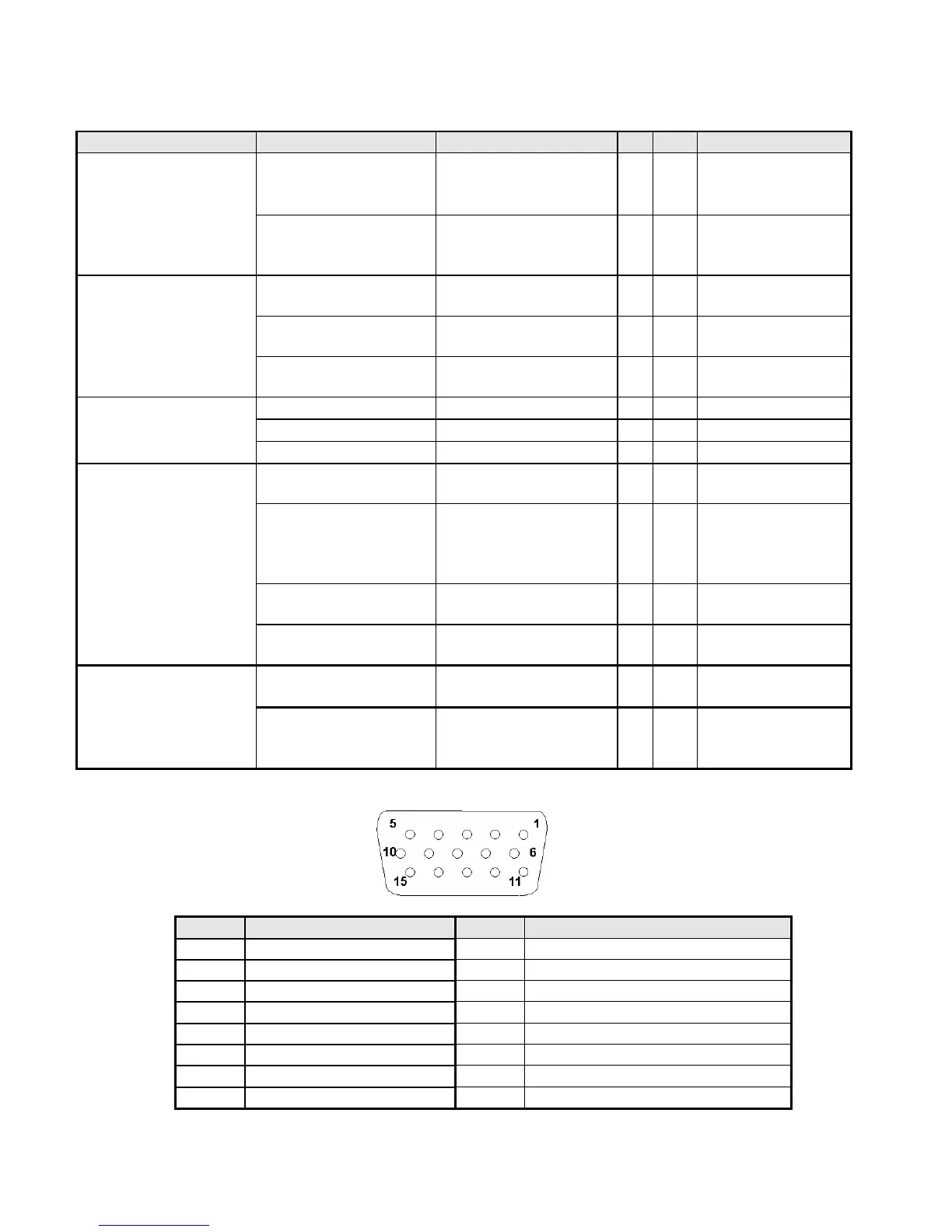
Note-1: The pin assignment of 15-pin D-sub connector is as below,
Pin Signal Assignment Pin Signal Assignment
1 Red video 9 PC5V (+5 volt power)
2 Green video 10 Sync Ground
3 Blue video 11 Ground
4 Ground 12 SDA
5 Cable Detected 13 H-Sync (or H+V)
6 Red Ground 14 V-sync
7 Green Ground 15 SCL
8 Blue Ground
 Loading...