- 8 -
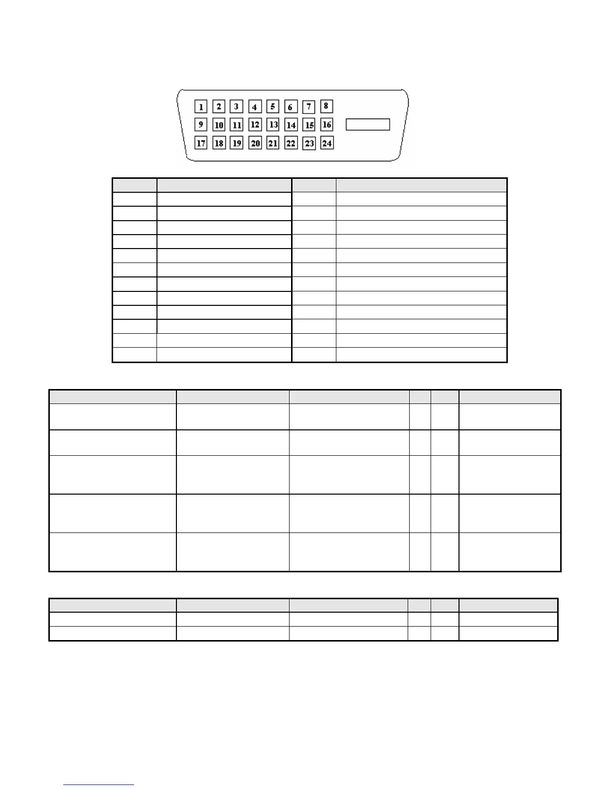
Note-2: The pin assignment of 24-pin DVI-D connector is as below,
Pin Signal Assignment Pin Signal Assignment
1 TMDS RX2- 13 Floating
2 TMDS RX2+ 14 +5V Power
3 TMDS Ground 15 Ground
4 Floating 16 Hot Plug Detect
5 Floating 17 TMDS RX0-
6 DDC Clock 18 TMDS RX0+
7 DDC Data 19 TMDS Ground
8 Floating 20 Floating
9 TMDS RX1- 21 Floating
10 TMDS RX1+ 22 TMDS Ground
11 TMDS Ground 23 TMDS Clock+
12 Floating 24 TMDS Clock-
3.2.3 Video performance
Item Condition Spec OK
N.A
Remark
Max. support Pixel rate
135 MHz
√
Both for analog and
digital inputs
Max. Resolution
1366 x 768
√
Both for analog and
digital inputs
Rise time + Fall time
< 5 ms
(50% of minimum pixel
clock period)
√
1366 x 768 @ 60Hz
(max. support
timing)
Settling Time after
overshoot /undershoot
< 5% final full-scale
value
√
Refer to VESA
VSIS Standard
V1R1
Overshoot/Undershoot
< 12% of step function
voltage level over the
full voltage range
√
Refer to VESA
VSIS Standard
V1R1
3.2.4 Scan range
Item Condition Spec OK
N.A
Remark
Horizontal
31-80KHz
√
Vertical
55-76 Hz
√
 Loading...