Single Phase Power Requirements
Nominal AC Voltage Minimum AC Volts Maximum AC Volts HP Input A
RMS
Output A
RMS
230 200 264 2.0 11.05 5.29
Note: Internally, the Speed Controller provides 240VAC 3 phase at 8kHz switching frequency to the motor.
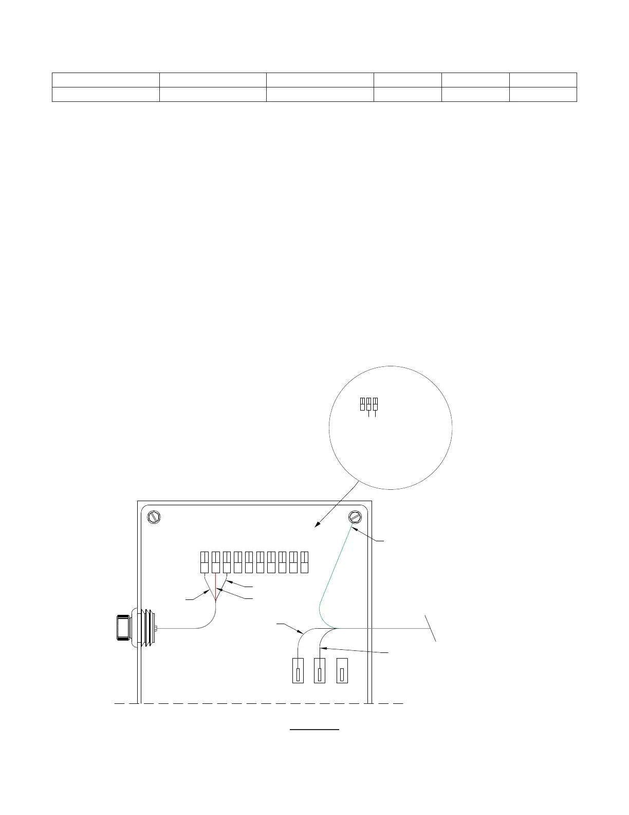
Speed Dial Wiring Diagrams
Mounted Speed Dial – (See Figure 16) Standard potentiometer speed
dial is mounted and wired at the factory.
For eld replacement: Connect the Speed Control Potentiometer to
the motor control as follows:
a. Connect one end of 10K Potentiometer to P10-1 (24VDC).
b. Connect center (wiper) of Potentiometer to P10-2 (Analog Input)
c. Connect other end of Potentiometer to P10-3 (DGND).
Remote Speed Dial** – (See Figure 17 & 18) Factory mounted
Molex receptacle allows a quick connection to remote potentiome-
ter speed dial. The potentiometer dial can be mounted up to 100 ft
from fan using additional wire by others.*** Speed B on box is not
used for single speed selection and will not have a dial.
Dual Speed Dial** – (See Figure 19) Factory mounted Molex recepta-
cle that allows a quick connection to Dual Potentiometer Speed Dial.
The supplied unmounted toggle switch will select the Low (LO) or High
(HI) speed on the speed controllers based on the dial settings. Toggle
switch and mounting plate t in a standard gang box and wired to Dual
Potentiometer Speed Dial. The speed dial can be mounted up to 100 ft
from fan using additional wire by others.***
Building Control 0-10VDC Wire Kit – (See Figure 20) Factory mount-
ed Molex receptacle that allows a quick connection to supplied 2 wire
connector (wires are 3” long).
**Disconnects and Speed Dials are available as mounted on certain fan
models and will be wired to motor, for more information see descriptions
on submittals for these items weather they are mounted, not mounted
or not available
*** For extended wiring up to 100 Feet you will need (1) Receptacle
Molex 3 1396-R4 with 3 Pin Female Molex 02-09-1119 and (1) Plug
Molex 3 Pin 1396-P1 with Pin Male Molex 02-09-2118 not provided.
1 2 3
4
5 6 7 8 9 10
12V
ANG1
DGND
ANG2
DGND
LGX1
LGX2
LGX3
LGX4
DGND
White
Red
Black
L2
Motor Mounted Potentiometer
(Standard)
L1
N
Black
Green -
Ground
White
Line Voltage
208-230 VAC
Single Phase
Motor Control Box
1098
LGX3
LGX4
DGND
Jumper:
Pin 9 = Dl 1 - Run Enable
Pin 10 = GND
Note: Jumper can be replaced by
switch or other dry contact
actuator for remote run enable
control
14 AWG
NOTE: Applies
to both Figure 16
and Figure 17
Page 12
FIGURE 16