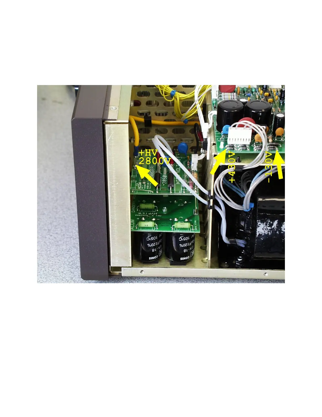
2. Discharging HV capacitors.
Using a piece of wire connected to the rear-panel grounding stud, DISCHARGE
residual charges from THE HV CAPACITORS (if any) by short-circuiting the three
points shown in the picutre below.
3. Installing the top cover.
a) Using a Philips-1 screwdriver, unscrew 15 countersunk-head screws and
remove the RF screen from RF deck. Put the cover on the chassis while
holding its rear edge lifted slightly (to 2-3cm) above the chassis.
Align its horizontal and two vertical front edges to the respective
chutes in the front panel. Then push gently the cover forwards, in order
to insert its front edges into the chutes. Take care especially to the
bottom corners.
b) Screw in loosely all 9 pcs of "eco-fix" flange-button head screws. Use a
Philips-2 screwdriver.