Do you have a question about the Acom ACOM1000 and is the answer not in the manual?
Provides an overview of the ACOM1000 HF+6 meters linear amplifier and its capabilities.
Details contact information for obtaining assistance and support from ACOM specialists.
Lists the items included with the ACOM1000 amplifier shipment.
Highlights the main operational and design advantages of the linear amplifier.
Outlines safety precautions and defines terms like WARNING, CAUTION, and NOTE for safe operation.
Instructions for safely unpacking the amplifier and checking for any physical damage.
Guide on selecting the correct line voltage setting for the amplifier to prevent damage.
Recommendations for positioning the amplifier for optimal performance and ventilation.
Step-by-step instructions for connecting the amplifier to the station and antenna system.
Details on when and how to install the optional external cooling fan.
Step-by-step guide for powering the amplifier on and off safely and correctly.
How to switch between operate and standby modes, with and without Auto-Operate.
Detailed procedure for tuning the amplifier for optimal performance using the TRI aid.
Accessing and using the amplifier's various operational screens and control functions.
Explanation of the amplifier's automatic protection mechanisms and trip levels.
How to adjust the LCD display's contrast and backlighting for readability.
Instructions for enabling or disabling the automatic operate function.
Method for accessing and interpreting stored auto-protection trip signatures for diagnostics.
Guidelines for safely cleaning the exterior of the amplifier.
Information on replacing the primary mains fuses and other internal fuses.
Guidance regarding the replacement of the amplifier's internal tetrode tube.
Reference to the simplified schematic diagram for understanding internal circuitry.
Methods for diagnosing issues using auto-protection signatures and general troubleshooting.
Detailed technical specifications covering frequency, power, distortion, and impedance.
Lists the key functions and features of the ACOM1000 amplifier.
Recommendations for storing and shipping the amplifier to maintain its condition.
The ACOM1000 HF+6 meters Linear Amplifier is a self-contained device designed to enhance amateur radio operations across all bands from 1.8 to 54 MHz. It delivers over 1000W output power with less than 60W exciter drive, accommodating antenna VSWR up to 3:1 at full power.
The amplifier's primary function is to amplify radio frequency (RF) signals, providing significant power output for amateur radio transmissions. It incorporates a plate-load True Resistance Indicator (TRI) and an automatically controlled input attenuator to simplify antenna matching. Operating parameters are displayed on a multi-functional backlighted Liquid Crystal Display (LCD). Full break-in transmit/receive switching (QSK) is a standard feature, ensuring seamless operation.
The ACOM1000 is designed to operate without requiring special signals from the transceiver, needing only a "ground on TX" signal and 60W RF drive power. It features a broadband input matching circuit that provides a good load to the transceiver across the entire 1.8MHz to 54MHz spectrum. The amplifier uses a single 4CX800A (GU74B) Svetlana high-performance ceramic-metal tetrode, which has a plate dissipation of 800W and is grid-driven with forced air cooling.
The device continuously monitors and protects plate and grid voltages and currents, as well as exhaust air temperature. A Bias Optimizer reduces heat dissipated from the tube, and automatic protection against overheating is implemented according to tube specifications. An output RF Arc protection system safeguards the amplifier, antenna, antenna selector, and tuner from severe damage in case of a breakdown. High voltage power supply inrush current protection is also included to prevent affecting other sensitive devices on the same mains circuit, which is particularly useful for portable operations. The amplifier can be configured for five nominal line voltages: 200, 210, 220, 230, and 240VAC, 50 or 60Hz (with 100, 110, and 120VAC available upon request). It continuously measures and/or monitors 12 important parameters of the amplifier, exciter, and antennas via the LCD.
The ACOM1000 is designed for ease of use. The TRI acts as a powerful tuning aid, enabling quick and precise antenna matching (typically 5-10 seconds). The auto-operate function, when enabled, automatically maintains the amplifier in OPERATE mode, reducing manual intervention. This eliminates the need for heavy outboard antenna tuners for VSWR up to 3:1, allowing faster antenna changes and use over wider frequency ranges.
The amplifier is robust, designed to safely withstand up to 500W reflected power, drive spikes of up to 100 milliseconds, RF "tails" after PTT or KEY release, and operator tuning errors. It can deliver more than half power even with a "soft" AC line at 75% of nominal mains voltage and can withstand voltage drops of up to 10 milliseconds (down to zero) and line voltage spikes of up to +15%, making it suitable for field days and DXpeditions.
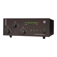
All amplifier status indications are provided through detailed text on the dot matrix backlighted LCD. The upper line of the LCD consistently displays peak forward power. LED indicators show OPERATE, attenuation-on, and ON/OFF conditions. The amplifier generates less noise in the shack due to input bypassing and virtually silent vacuum antenna relays, even in QSK CW mode. Antenna matching can be achieved in under 10 seconds at a quarter of nominal output power, reducing QRM and improving electromagnetic compatibility during tuning.
The amplifier offers 14 ON LINE information screens, selectable via PREV or NEXT buttons, to monitor various parameters like Forward Power, Reflected Power, Output Power, Antenna VSWR, Drive RF Power, RF Power Gain, Plate Current, High Voltage, Plate RF Peak, Screen Current, DC Power Input, and Exhaust Air Temperature (in Celsius and Fahrenheit). These screens help monitor the technical state of the amplifier and associated parameters in digital form. LCD contrast and backlighting can also be adjusted while ON LINE.
The auto-protection system provides three degrees of protection for abnormal conditions. The first degree issues a warning message without interrupting transmission (e.g., "Reduce Drive," "Plate Current"). The second degree results in a trip to standby mode (Soft Fault), displaying messages like "** GRID CURRENT **" and flashing the LCD backlight. These soft faults can often be corrected by adjusting operating conditions. The third degree is a trip to off mode (Auto-Protection), displaying a corresponding signature. The 6dB input attenuator is automatically inserted about one second after bad tuning is detected at drive levels above 20W and switches off upon PTT release (unless manually inserted).
The ACOM1000 stores signatures of its internal status in nonvolatile memory for the seven most recent auto-protection trips. This information can be used for diagnostics by forwarding it to a dealer or by decoding it yourself using an EXCEL APPLICATION available from ACOM or your dealer.
For cleaning, only the amplifier's outer surface should be wiped with a soft cotton cloth lightly moistened with clean water. Solvents should not be used, and the amplifier should not be opened for cleaning.
The two primary mains fuses are located on the rear panel and are 10A/250V Quick blow, 1-1/4 x 1/4 inch Cartridge Fuses, Size "0" Ceramic. If replacement is necessary, only standard ones should be used. The amplifier also contains two smaller glass fuses (5x20mm, 100mA and 2A slow-blow type) on the MAINS PCB, which are not user-replaceable. If these fuses blow, it may indicate other failures, and this complex operation should be performed by a trained service technician.
Tube replacement, involving the single 4CX800A (GU74B) tetrode, is also a complex and potentially dangerous operation that should be carried out by a trained service technician.
For shipping, the original packing should be used. The amplifier should be switched off, unplugged, and all cables disconnected before packing. It can be stored in dry, ventilated, unheated premises free from chemically active substances.
| Power Output | 1000 W PEP |
|---|---|
| Input Impedance | 50 Ohms |
| Output Impedance | 50 Ohms |
| Cooling | Forced air |
| ALC | Yes |
| Frequency Range | 1.8 - 29.7 MHz |
| Harmonic Output | -50 dB |
| Tube | 4CX800A |