Do you have a question about the Acom ACOM2100 and is the answer not in the manual?
Describes the amplifier's purpose and key capabilities.
Provides contact details for technical support and inquiries.
Details the items included in the amplifier package.
Highlights the amplifier's main operational and technical capabilities.
Outlines safety precautions and defines warning terms.
Steps for unpacking and checking for damage.
How to set the amplifier for the correct mains voltage.
Refers to Appendix A for transformer mounting instructions.
Guidance on choosing a suitable operating location.
Step-by-step guide for connecting the amplifier to the station.
Instructions for installing an optional cooling fan.
How to turn on the amplifier and the warm-up process.
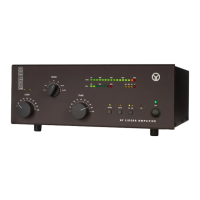
Overview of buttons, LEDs, and the OLED display.
Managing the amplifier's operational states.
How to switch between connected antennas.
Steps to match antenna impedance for optimal performance.
Guidelines for modes like RTTY and SSTV.
Accessing status screens and functions while operating.
How the amplifier detects and responds to faults.
Setting automatic mode switching.
Configuring which antenna outputs are active.
Accessing fault logs.
How to clean the external surfaces safely.
Steps for replacing internal and external fuses.
Guidance for replacing the amplifier tube.
Reference to the circuit diagram.
How to interpret protection signatures and solve issues.
Detailed technical specifications of the ACOM2100.
Overview of the amplifier's features and capabilities.
Instructions for safe storage and transport.
Step-by-step guide for installing the transformer.
How to set jumpers for the correct mains voltage.
| Frequency Range | 1.8-54 MHz |
|---|---|
| Gain | 13dB |
| Cooling | Forced air |
| Input Impedance | 50 Ω |
| Output Impedance | 50 Ohms nominal |
| RF Gain | 13 dB |
| Primary Power | 50-60 Hz |
| Tube | 4CX800A |
| Harmonic Suppression | -50 dB |
| Hum and noise | Better than 40 dB below rated output |