p.9 of 14
ACOM 1010 Technical Suplement
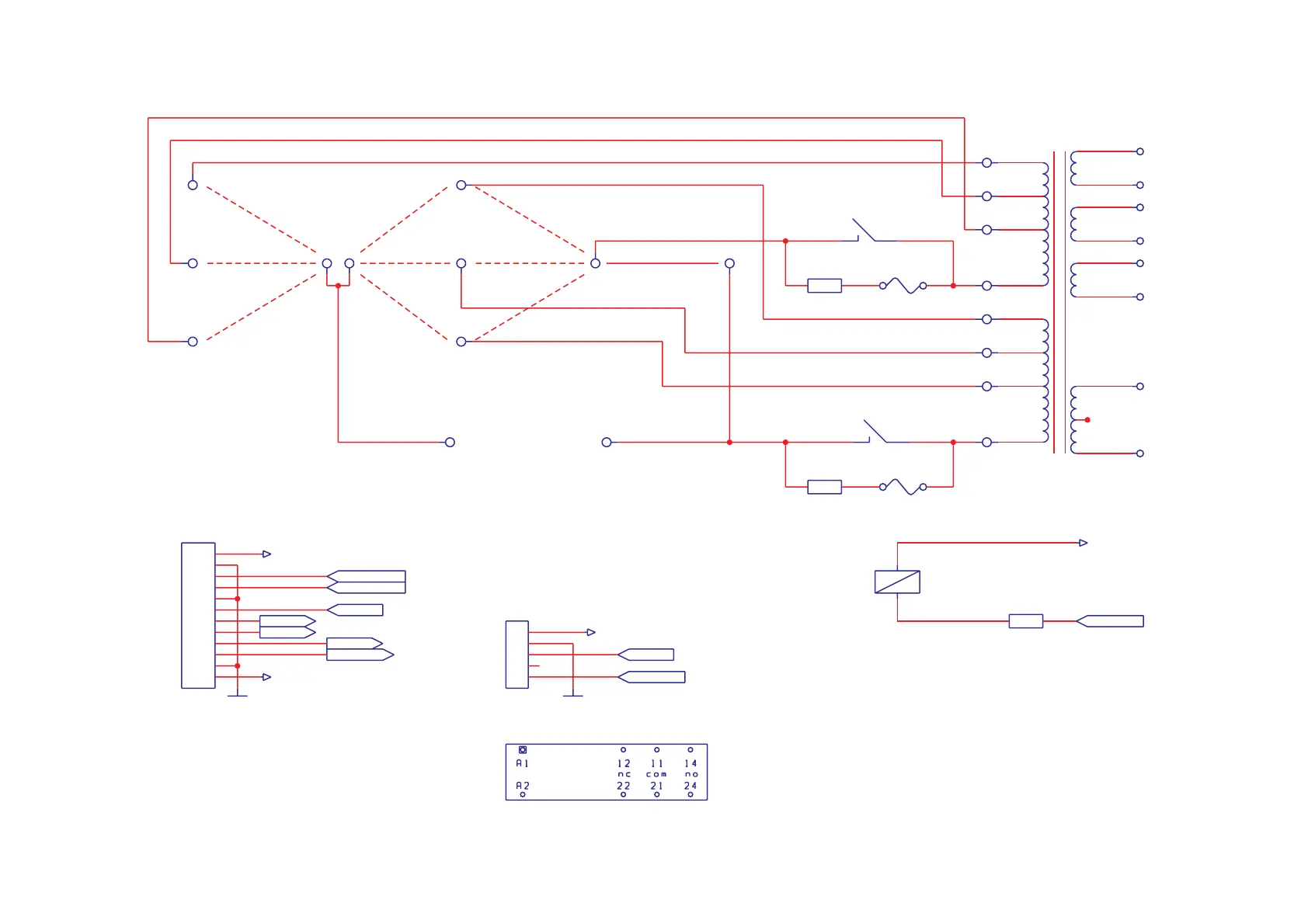
Appendix A
MAINS&LV POWER SUPPLY
Schematic diagram Sht. 1 of 4
13.2V
T9
10V
TV1
T1
120,240V
A1
A2
MB
MA
120V
A5
A6
230,240V
A4
A8
K1A
RTE44012
11
14
10V
100V
T2
T3
92V
T10
T11
T12
(To HV PCB)
(To
HV
PCB)
270V
T13
T14
10V
10V
T4
T5
T6
F1
0.8ASB
R1
22/7W
100,110,120V
100V
200V
210,220V
A7
110V
100,200,210V
110,220,230V
A3
Mains Input
Mains
Input
M1
M2
K1B
RTE44012
21
24
100V
T7
T8
830V
830V
(T16,T17)
T15
(To HV PCB)
(To
HV
PCB)
+15V
T18
F2
0.8ASB
R2
22/7W
Voltage
1
2
3
4
5
6
7
8
9
10
11
12
JP1
CONTROL
g2warn
ipg2
g1warn
G1VL
ENAB
RTTY
+5V
1
2
3
4
5
JP2
TUBE DECK
TUBE
DECK
GND
+15V
K1C
RTE44012
A1
A2
R3
120
*STST
n/c
+265V
BIAS
BOTTOM VIEWBOTTOM
VIEW
RTE 44012RTE
44012
RTE44012(F) - hermeticRTE44012(F)
-
hermetic
Finder: 41.52.9.012.0311 - hermeticFinder:
41.52.9.012.0311
-
hermetic
Finder: 41.52.9.012.0310 - non-hermeticFinder:
41.52.9.012.0310
-
non-hermetic
Schrack (Potter&Brumfield):Schrack
(Potter&Brumfield):
RT444012(F) - non-hermeticRT444012(F)
-
non-hermetic
*STST
+15V