32
Not all transceivers correctly report VFO A and VFO B when in split mode. If your transmit and
receive frequencies are in different band segments and the amplier retunes on every RX/TX
transition, turn off the CAT until the end of the split operation.
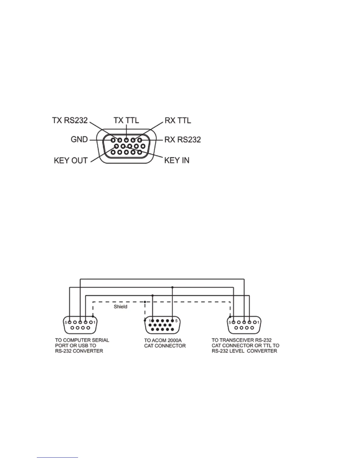
The CAT connector is located on the RCU rear panel. Besides the RS232 and TTL compatible
serial interface, the CAT connector also carries the KEY IN and KEY OUT lines, which can be
used instead of using separate cables for those functions from the transceiver to the sockets
of the same names. See Figure 7-1 below:
Fig. 7-1 CAT Connector pin-out front view
Many transceivers have different connectors and different signal levels. To be sure that your radio
will interface properly with the 2000A, the connection cable should be prepared according to
Fig.7-1 and the corresponding information from your transceiver’s user manual. Here are some
examples. Please note that the front view of the cable connectors is shown in these pictures.
- Y serial cable. When the CAT port of the transceiver is used for another device such
as a computer or an antenna controller, a Y cable should be used. An example is shown on
Fig. 7-2. Use only shielded cables for all connections. Note that the amplier will receive correct
data only when the CAT connection between the transceiver and the other device (for example,
a computer with running logging software) is active.
Fig. 7-2 CAT Connection by RS-232 Y cable
- ICOM CI-V Interface: A 3.5mm audio stereo plug, a two conductor shielded cable
and two 510 Ohm resistors are required. The wiring is shown on Fig. 7-3.
Pin 1 – RX RS232
Pin 2 – RX TTL
Pin 3 – TX TTL
Pin 4 – TX RS232
Pin 5 – GROUND
Pin 9 – KEY IN
Pin 10 – KEY OUT