COMPONENT TESTING PROCEDURES
To avoid risk of electrical shock, personal injury or death; disconnect power to oven and discharge capacitor
before servicing, unless testing requires power.
Discharge Capacitor
Remove all wires from terminals.
Measure resistance from:
230 to COM ..........................................
208 to COM ..........................................
230 to Ground
208 to Ground----------------------------------
Terminal 5 to 6---------------------------------
Terminal 7 to 8---------------------------------
Terminal 4 to Ground-------------------------
Less than 1
Less than 1
Infinite
Infinite
Less than 1
Less than 1
Approximately 27
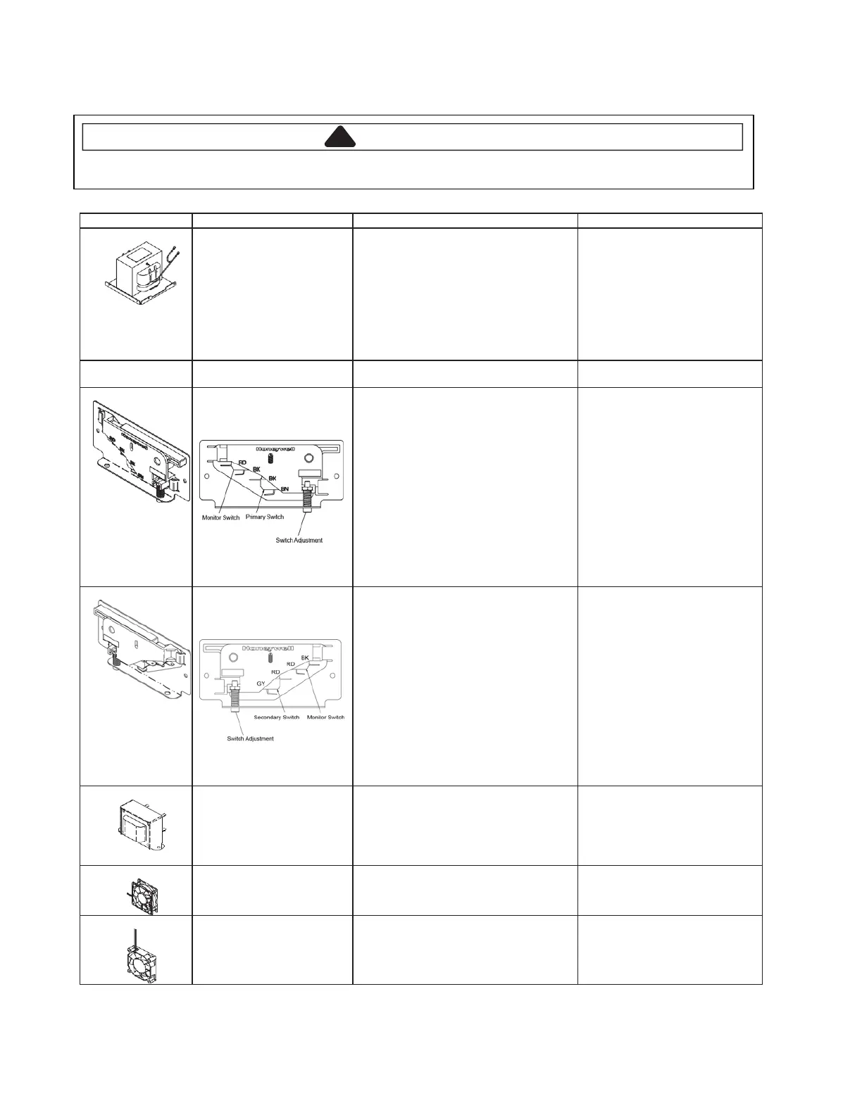
Left interlock switch assembly
Disconnect wires to switch.
With door open measure resistance from:
Monitor – Terminals Rd- Bk..............
Primary – Terminals Bk - Brn ...........
With door closed measure resistance from:
Monitor – Terminals RD - BK ...........
Primary – Terminals BK - BN ...........
After verifying or replacing the
assembly, re-connect wires to switch
and check operation of monitor circuit
before operating the oven.
Indicates continuity
Infinite
Infinite
Indicates continuity
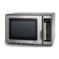
Right interlock switch
assembly
(Mechanical)
Disconnect wires to switch.
With door open measure resistance from:
Monitor – Terminals RD- BK ............
Secondary – Terminals GY -RD.......
With door closed measure resistance from:
Monitor – Terminals RD - BK ...........
Secondary – Terminals GY - RD......
After verifying or replacing the
assembly, re-connect wires to switch
and check operation of monitor circuit
before operating the oven.
Indicates continuity
Infinite
Infinite
Indicates continuity
(1) BU to (5) BR ----------------------------- --
Approximately 40 or Line Voltage
(6) YL to (10) WH-------------------------------
Approximately 1 or 28 VAC
Disconnect connector from fan.
Measure voltage at incoming leads ...........
Disconnect connector from fan.
Measure voltage at incoming leads .......