Component Specifications
!
WARNING
To avoid risk of electrical shock, personal injury, or death, disconnect power to oven and discharge capacitor
before servicing, unless testing requires power.
16500051 January 2013
©2013 ACP, Inc.
4
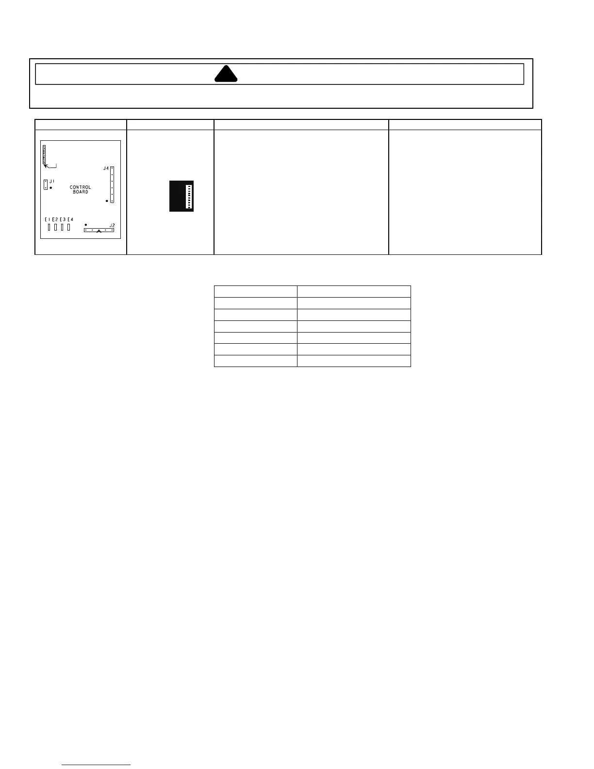
Illustration Component Testing Results
CONTROL
BOARD
J2
J1
J4
E1 E2 E3 E4
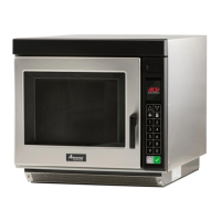
Pin #1
P1
Controller board
P1 connector used
for touch panel
ribbon
Line voltage to control board
E1—E3 ................................
Output drive voltage to triac
Triac terminals ................................
Gate—T1 ................................
Fan relay (controls blower motor, antenna
motor(s), and oven light)
Control board ................................
Terminals J4-1—J2-2
................................
Cook relay
Control board ................................
Terminals E1—E4................................
Line voltage (All Conditions).
0 VAC (Idle and Standby).
0.9 VAC (Cook).
Line voltage (Idle).
0 VAC (Standby and Cook).
Line voltage (Idle).
0 volts (Standby and Cook).
Error Code Table
Error Code Corrective Action
F1 Replace HV/LV Board
F2 Replace HV/LV Board
F3 Replace HV/LV Board
F4 Replace HV/LV Board
F5 Replace Touch Panel
F6 Replace HV/LV Board
Initial Power Up Condition: Apply power to oven with door closed.
Idle Condition: Oven plugged in, display blank (no other components operating).
Standby Condition: Open oven door, light and motors operate.
Cook Condition: Food load in oven, cook cycle initiated.