1.1 SA220P front panel features
Acqiris SA220P User's Manual 9
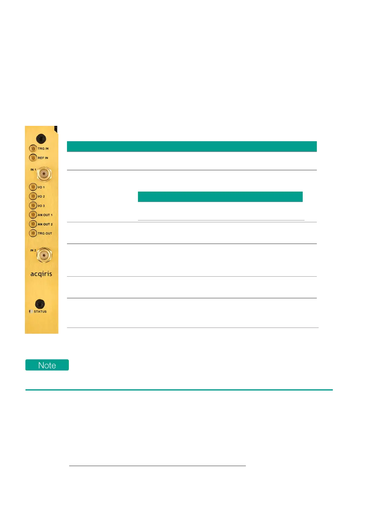
1.1 SA220P front panel features
Front panel connectors
Connector Type Description
TRG IN
MMCX
female
External trigger input, 50 Ω DC terminated, ± 5 V range.
IN 1, 2
SMA
female
Analog signal inputs, DC-coupled and 50 Ω terminated. The input full scale
ranges are selectable:
Voltage 500 mV FSR 2.5 V FSR
Recommended maximum
operating voltage
± 600 mVpk ±3 Vpk
TRGOUT
1
MMCX
Trigger Out signal (programmable).
50Ω source, LVCMOS 3.3V
I/O 1, 2, 3
MMCX
User configurable digital Input / Output signal.
DC coupling, LVCMOS 3.3 V.
Output: 50Ω source, Input: +5V max.
REF IN
MMCX
External reference clock input, AC coupled and 50 Ω terminated.
It can accept a 10MHz or a 100 MHz signal from -3 to +3 dBm.
AN OUT 1, 2
MMCX
Application dependent analog signal from a 12-bitDAC, controlled by the
internal FPGA.
DC coupling, 300 Ω source, programmable output up to ± 10V.
Table 1.1 - List of SA220P front-panel IOs.
The ADC card can usually work with signal present at the external reference input (REF IN).
However, to ensure the best performance, or if the calibration is found to be unreliable, it is
recommended to remove such signals when working with internal clock.
1
The trigger out connector depends on the product version.