Unit 8 IDA Business Park, Whitestown, Tallaght, Dublin 24, Ireland.
Telephone: 353 1 462 2585. Telefax: 353 1 462 2587. E-mail: sales@accesscontrol.ie Web: www.accesscontrol.ie
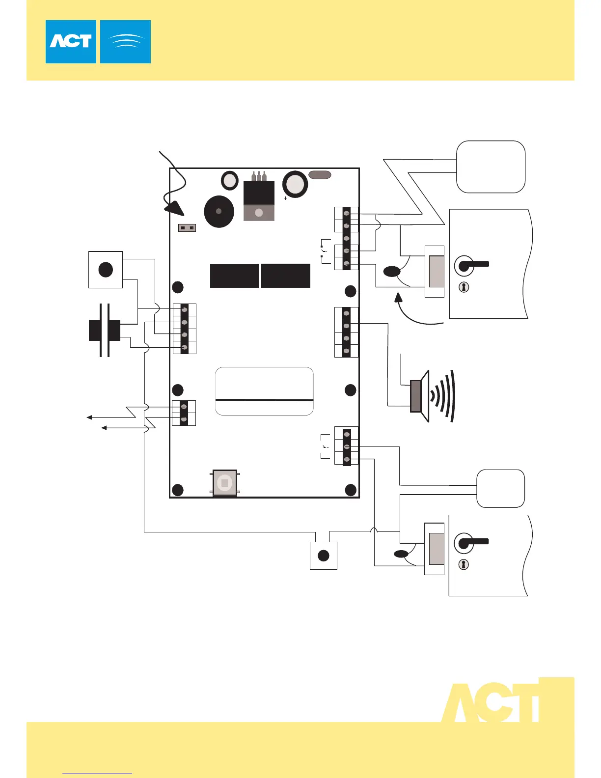
Typical ACT10 Configuration
(Normally de-energised lock shown)
!
OMRON
5A 250VAC
5A 30VDC
0123456789
Important
Always Place Varistor
Across All Lock Terminals
+V
Power up withou t link if
Programming code has been lost.
+V
0V
Volt - Free
Tamper Contacts
Door Contact
Door Release
Button
Guest Buzzer
Power Supply
12-24V ACDC
This diagram shows revision (3.1) of the ACT10
This unit may be used to control 2 doors as illustrated in the
diagram above.
Connections and programming for this unit are exactly the
same as for previous versions, however the connector
positions have changed as shown in the above diagram.
12-24
AC/DC
-
+
N/C
N/O
C
0V
Buzzer
OP3
Duress
OP2
Interlock
OUTPUTS
INPUTS
0V
Interlock
(PB2)
Push
Door
Contact
Button
TAMPER
LK1
Serial No. 12345
Batch: 20xx-1
Product:ACT10 Rev3.0
N/C
N/O
C
+V
0V
Door Release Button
for Door 2
RELAY
DOOR 2
OMRON
5A
250V
AC
5A 30VDC
Door 2
12-24V ACDC
Power Supply