Copyright © 2016 Access Control Technology Ltd. Part No.18-00100 Issue 1.0
4
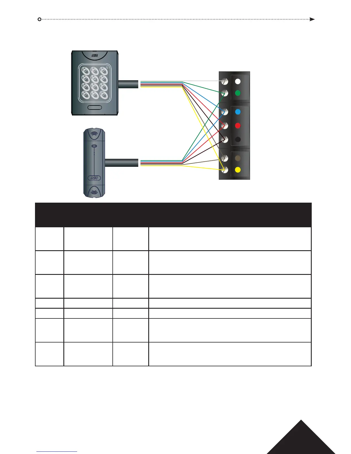
Wiring of entry & exit readers.
For Wiegand Entry Readers wire D0 to DATA Pin on ACTpro Door Station and D1 to
CLOCK pin on ACTpro Door Station.
For Wiegand Exit readers wire the D0 of the exit reader to SENSE pin on ACTpro Door
Stationand D1 to CLOCK pin on ACTpro Door Station.
SENSE
CLOCK
DATA
+12V
OV
RED
GREEN
Entry Reader
Exit Reader
(Do not connect to SENSE)
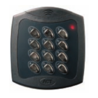
ACTpro 1050e
Pin & Proximity Reader
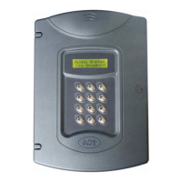
ACTpro 1030e
Proximity Reader
Reader Recommended Controller Signal information
Terminal wiring colour input Pin
Block
SENSE White SENSE For Entry readers connect the reader SENSE cable or
terminal to the SENSE input pin.
For Exit readers, do not use this input.
CLOCK Green CLOCK This is the clock or strobe signal input on the ACTpro
120e. Connect the reader CLOCK cable or terminal
on the reader to CLOCK input pin.
DATA Blue DATA This is the Data input.
Connect the reader DATA cable or terminal on the reader
to DATA input pin.
+12V Red +12V Positive +12V DC Supply voltage for the reader.
0V Black 0V 0V Supply Voltage for the reader.
RED Brown RED Red LED control output from the ACTpro 120e.
Connect the reader brown cable to the terminal marked
RED on the door station.
GREEN Yellow GREEN Green LED control output from the ACTpro 120e.
Connect the reader green cable or terminal marked
GREEN on the ACTpro Door Station.
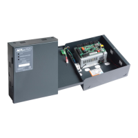
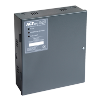
ACTpro 120e PSU Operating and Installation Manual