Hardware Manual
20
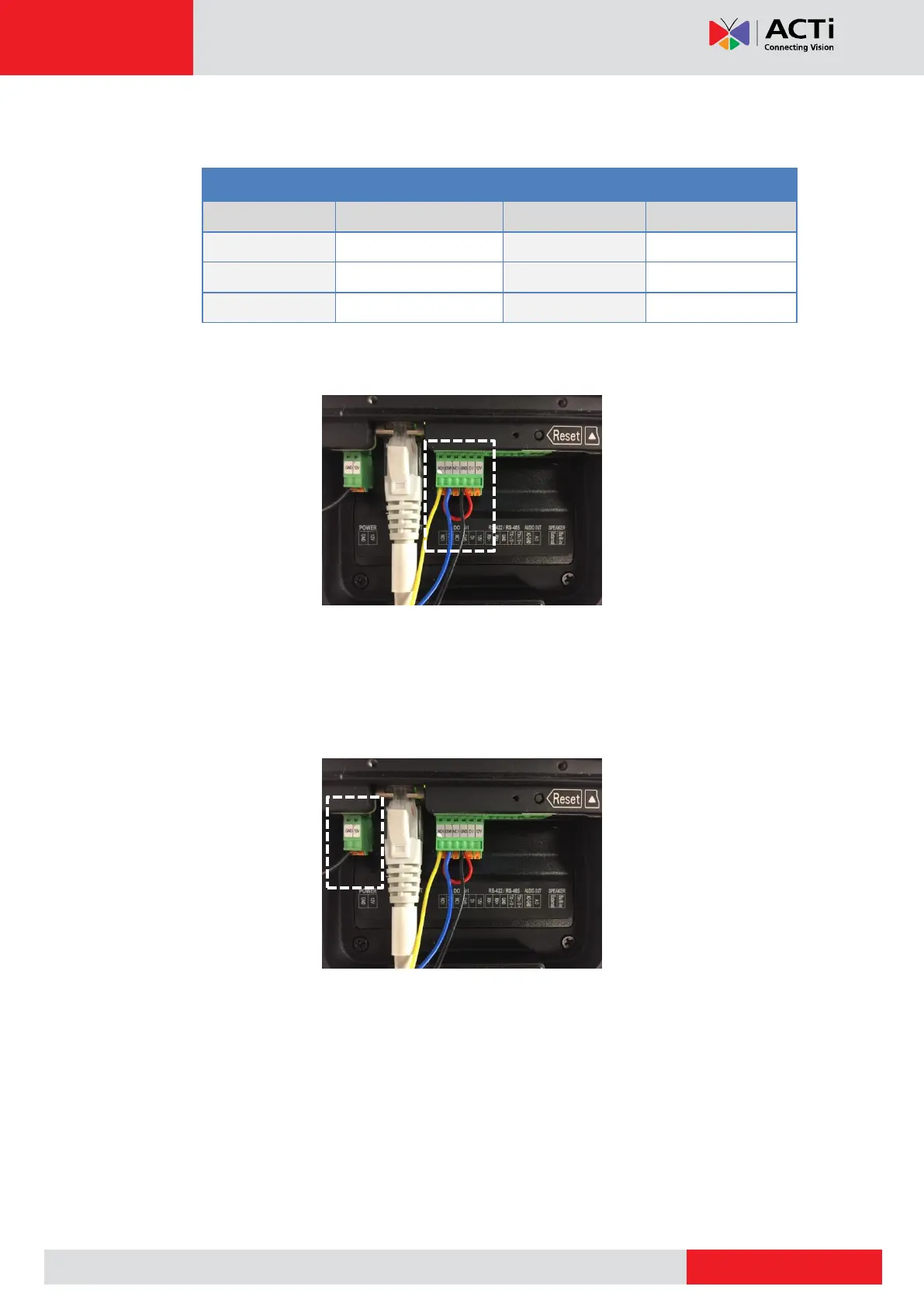
3. Map the appropriate wires:
a. Door lock wires to the pins on the bundled terminal block, as below:
b. Using another wire, map COM1 and GND pins of the terminal block; refer to the
curved red wire on the picture below:
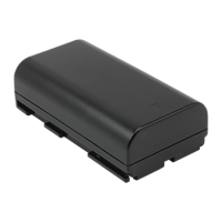
4. Power up the door lock to a DC 12V power separately; map the red wire on the door lock
to the DC12 V wire of the power adapter and map the ground wire of the power adapter to
any of the GND pin on the door station. Picture below shows the ground wire of the power
adapter connected to the GND pin of the door station (door station is powered by PoE in
this example).