IMPORTANT
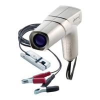
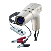
4. Connect RED and BLACK Battery Clips on Negative Ground Electrical
Systems.
· Connect RED to positive (+) battery post.
· Connect BLACK to engine ground.
On 6-volt electrical systems, use an auxiliary 12-volt battery to
power timing light. Connect BLACK clip to negative (-) post and
RED clip to positive (+) post on auxiliary 12- volt battery. Use 18
AWG or larger wire to connect 12-volt battery negative (-) terminal
to a good engine ground.
On 12-volt Positive Ground electrical systems, connect BLACK clip
to negative (-) battery post and RED clip to engine ground. DO NOT
USE the positive battery post.
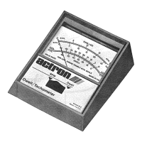
On engines equipped with a breaker point ignition system, it will be
necessary to set the point dwell before adjusting the timing. Always
follow the manufacturers specifications and test procedures for
adjusting dwell angle and idle speed.