Do you have a question about the ActronAir AIRES CRS10AS and is the answer not in the manual?
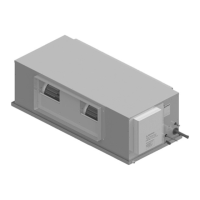
Provides installation instructions specific to your ducted unit. Read thoroughly for correct installation and safe operation.
Check unit and components against invoice for damage. Verify unit nameplate details.
Installer/contractor responsible for compliance with council, state/federal codes and building standards.
Highly efficient circuit delivering required cooling/heating with advanced components like twin rotary compressor and EEV.
EC fans provide superior airflow with efficient EC motors, low noise, and adjustable airflow.
Features DC axial fans, inverter compressor, low noise, variable capacity and speed.
Australian-made for extreme weather, with galvanized steel cabinet and hydrophilic coil fins.
Suitable for residential and commercial applications, new construction, or retrofitting projects.
Uses zero ozone-depleting refrigerant, reducing energy consumption and CO2 emissions.
Follow WH&S regulations, use PPE, avoid loose clothing, secure guards, and beware of moving parts.
Assess work areas for hazards and familiarize with unit parts before service tasks.
Never release refrigerant; recover, recycle, and reuse. Consult MSDS for safe handling.
Use refrigerant reclaiming equipment, pull vacuum below 500 microns.
Verify capacity, ensure solid foundation, allow clearances for airflow and service.
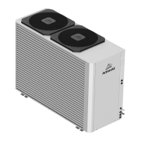
Diagram identifying key components of the CRS10AS outdoor unit.
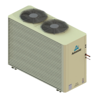
Diagram identifying key components of the CRS13AS/AT outdoor unit.
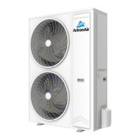
Diagram identifying key components of the CRS15AS/AT and CRS17AS/AT outdoor units.
Diagram showing the layout of the control panel for the CRS10AS model.
Diagram showing the layout of the control panel for the CRS13AS/AT model.
Diagram showing the layout of the control panel for CRS15AS/AT and CRS17AS/AT models.
Table showing unit dimensions (A, B, C, D, E, F) for various models.
Diagram illustrating refrigeration pipe distances.
Minimum recommended clearances for operational performance and service access.
Table listing net and gross weights for different unit models.
Recommended method for high-rise lifting using crane, including safety precautions.
Criteria for selecting an appropriate installation location for the outdoor unit.
Instructions for fixing the unit on ground level or bracket, with vibration rubbers.
Procedure for installing the drain joint if required, and ensuring drain line is clear.
Steps for connecting refrigerant pipes, including tightening flare nuts with torque.
Connecting power cable and signal control wire to terminal blocks.
Guidelines for brazing with nitrogen, ensuring cleanliness and proper evacuation.
Explanation and diagrams for calculating total equivalent field pipe length.
Procedure for nitrogen purging during pipe work installation to prevent carbon deposits.
Detailed steps for performing triple evacuation to remove moisture and non-condensables.
Wiring diagrams are located inside the electrical access panel.
Ensure compatible power supply, proper wiring, earthing, and circuit protection.
Check mains voltage balance to prevent motor overheating and premature failure.
Comprehensive wiring diagram for indoor and outdoor unit connections.
Diagram showing mains, inter-connecting power, and data cable connections for split units.
Instructions for connecting and shielding 2 core twisted data cable for communication.
Wiring details for LR7-1 and LC7-2 wall controllers.
Wiring details for NEO wall controllers, including hardwiring and RJ45 connections.
Wiring connections for the LM-RS-2 optional remote sensor.
Wiring connections for the AERSS optional duct sensor.
Describes Demand Response Management (DRM) modes and their operating parameters.
Guide to navigating the system menus for status and settings.
Configurable settings for control source: Third Party, Wall Control, Basic BMS, etc.
Details for controlling fan and compressor via 0-10V analogue input.
Controlling compressor with fixed indoor fan speed using 0-10V input.
External ON/OFF control for compressor and indoor fan.
External ON/OFF control for compressor with 0-10V indoor fan input.
Wiring for activating run/fault output signals from the outdoor board.
Wiring and procedure for activating remote ON/OFF control.
Fan data table, default speed, and PWM limits for EVA10AS.
Fan performance curve showing airflow vs. static pressure for EVA10AS.
Third party application fan curve for EVA10AS, showing PWM settings.
Fan data table, default speed, and PWM limits for EVV13AS/EFV13AS.
Fan performance curve showing airflow vs. static pressure for EVV13AS/EFV13AS.
Third party application fan curve for EVV13AS/EFV13AS, showing PWM settings.
Fan data table, default speed, and PWM limits for EVV15AS/EFV15AS.
Fan performance curve showing airflow vs. static pressure for EVV15AS/EFV15AS.
Third party application fan curve for EVV15AS/EFV15AS, showing PWM settings.
Fan data table, default speed, and PWM limits for EVV17AS/EFV17AS.
Fan performance curve showing airflow vs. static pressure for EVV17AS/EFV17AS.
Third party application fan curve for EVV17AS/EFV17AS, showing PWM settings.
Table of factory refrigerant charge (R-32) for different models.
Procedure for adjusting refrigerant charge using subcooling and superheat measurements.
Steps to measure and calculate subcooling to determine system charge.
Steps to measure and calculate superheat for optimal evaporator performance.
Instructions for recording final refrigerant charge on unit label and report.
Table correlating temperature and pressure for R-32 refrigerant.
Specifications for pipe sizes, lengths, and height differentials.
Details on refrigerant charge, pre-charge length, and minimum room area.
General guidelines for regular servicing by a licensed technician.
Checklist of tasks for annual maintenance inspections.
Procedure for cleaning condenser coils to maintain optimal performance.
Detailed steps for cleaning condenser coils, including precautions.
Checklist for electrical components including PCBs and connections.
Checklist for outdoor unit components like casing, fan, motor, and compressor.
| Cooling Capacity | 2.6 kW |
|---|---|
| Heating Capacity | 3.2 kW |
| Refrigerant | R32 |
| Power Supply | 220-240V, 50Hz |
| Operating Temperature Range (Cooling) | 18°C to 46°C |
| Operating Temperature Range (Heating) | -15°C to 24°C |
| Dimensions (Indoor) (HxWxD) | 270 x 790 x 195 mm |
| Dimensions (Outdoor) (HxWxD) | 495 x 720 x 270 mm |