Installation and Commissioning Guide - Split Ducted ESP Plus/Ultima Indoor Unit
Doc. No.0525-078 Ver. 2 190925
26
Installation and Commissioning Guide
Split Ducted ESP Indoor Unit
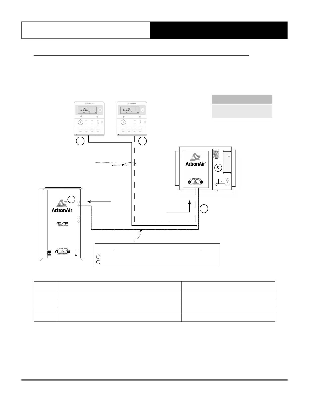
11. Wiring Connection Control Cable Length and Specification
NOTE
^ Available in White and Grey
colours
OPTIONAL
DUAL MASTER CONTROLLER
(Mimic Logic)
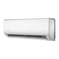
Master
Wall Control ^
Secondary
Wall Control ^
4A
2
4
TO INDOOR PCB
TO OUTDOOR PCB
4 CORE 14/0.20 (0.44mm)
Shielded Data Cable
3
8 ZONE
MO DULE
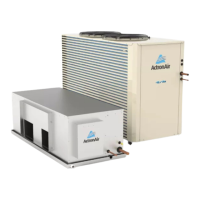
INDOOR UNIT
R-410A
“CAUTION”
PLEASE ENSURE THERE IS
NO GAS / PRESSURE IN THE
FAN COIL UNIT BEFORE
REMOVING COPPER END CAPS.
3570-043
ID OD FIELD DATA CABLE APPLICATIONS:
1
2 CORE 14/0.20 (0.44mm
2
) Shielded Data Cable
2
2 CORE 7/0.30 (0.5mm
2
) Twisted Pair Shielded Data Cable
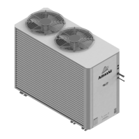
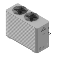
OUTDOOR UNIT
1
MODEL
R-410A
“CAUTION”
PLEASE THEREIS
NOGAS/PRESSUREINTHE
FANCOILUNITBEFORE
REMOVINGCOPPERENDCAPS.
ENSURE
3670-043
Sensor
4
CAUTION
LIVEELECTRICAL WIRING
AUTHORISEDTECHNICIANSONLY
INTERNAL CONTROL ISOLATORFITTED
MODEL
MEPS
CERTI FIED
A
U
S
T
R
A
L
I
A
N
M
A
D
E
A
U
S
T
R
A
L
I
A
N
O
W
N
E
D
R-410A
ITEM DESCRIPTION MAXIMUM CABLE LENGTH *
1 to 2 Outdoor PCB to Indoor PCB 60 m
2 to 3 Indoor PCB to 8-Zone Module (factory fitted) 0.60 m
2 to 4 Indoor PCB to Master Wall Control 40 m
2 to 4A Indoor PCB to Secondary Wall Control 40m (Including 2 to 4) **
*
Suggested Maximum Cable Length
Long runs beside Mains cables or TV antenna cables should be avoided where possible.
**
Total Cumulative Cable Length with Secondary Controller must not exceed 40 meters.
For example, if 2 to 4 is 30m then 2 to 4A must not exceed 10m.
NOTES:
• Trace wire connects to SCN/COM terminal at Outdoor PCB and to SCN on Indoor PCB. Do not connect at
Wall Controls.
• Diagram shown above is a general presentation only. Refer to individual unit wiring diagram for complete
wiring connection details.