Do you have a question about the ACV PRESTIGE Series and is the answer not in the manual?
Details who the manual is intended for, including end users, installers, and maintenance personnel.
Explains the meaning of symbols used in the manual for operation and safety.
Provides essential safety information, including gas leak procedures, temperature warnings, and installation guidelines.
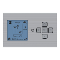
Covers basic operation, burner start/stop, heating system pressure, and control panel overview.
Guides users on how to adjust hot water temperature, heating modes, and central heating temperature settings.
Explains how the system detects faults, displays error codes, and how to reset the appliance.
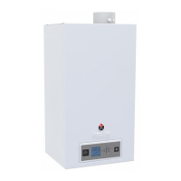
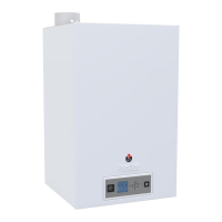
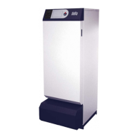
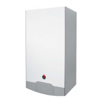
Details the specifications, lining, heat exchanger, burner, and temperature regulation of the appliance models.
Explains the integrated frost protection system and how to ensure efficient protection for the whole system.
Presents technical specifications for central heating, flue gases, gas, hydraulics, dimensions, and electrical connection for natural gas models.
Details technical data for propane models, covering central heating, flue gases, gas, hydraulics, dimensions, and electrical connection.
Provides operational data and features for domestic hot water production for AquaSpeed and Excellence models.
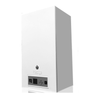
Specifies important considerations for the physical placement of the appliance, including air vents and product storage.
Outlines requirements for easy access to the appliance for servicing and maintenance, including minimum distances.
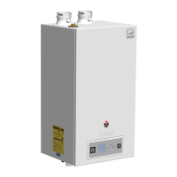
Provides detailed dimension drawings for Solo/AquaSpeed and Excellence models, showing connection points.
Describes the assembly panel, its components, and its function in integrating the appliance with heating circuits.
Details regulations and calculations for connecting the appliance to the chimney system, including flue resistance.
Illustrates various chimney connection types (C13, C33, C43, C53) and ventilation configurations (B23).
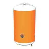
Explains how to connect the Prestige Solo to the hot water system and related settings for tank integration.
Details the connection of the AquaSpeed model to the domestic hot water circuit, including safety requirements.
Describes the connection of the Excellence model to the domestic hot water circuit, including safety units.
Provides instructions for connecting the appliance to the gas supply, emphasizing compliance with standards and checks.
Guides on flushing the system, connecting the appliance, managing pump speeds, and filling the system.
Details electrical connection requirements, supply voltage, and optional connections for thermostats and alarm units.
Presents a wiring diagram illustrating the functional connections of the appliance's components and sensors.
Outlines the steps for filling, draining, and checking the system, including gas pressure and CO2 settings.
Describes how to verify parameter settings and boiler settings, emphasizing the need for qualified installers.
Provides instructions for dismantling and cleaning the burner, electrode, and heat exchanger for optimal performance.
Guides on safely dismantling key components like the burner, electrode, and exchanger for servicing.
Detailed steps for removing and reassembling the heat exchanger, including draining and handling residual water.
Specific instructions for dismantling the mini-tank in the AquaSpeed model, covering connections and removal.
Explains the standard MCBA mode, status indicators, and burner block conditions, including temperature parameters.
Lists error codes, their descriptions, and resolutions for safety stop conditions, including how to unlock the system.
Details how to access and adjust user-accessible parameters for temperature and heating modes.
Lists advanced parameters available to specialists, covering frost protection, heating curves, and system settings.
Explains how to access special modes and parameters by entering a service code.
Describes how to use the 'Info mode' to retrieve installation data and parameter values.
Explains how to check communication status between the boiler, control module, and other devices.
Details how to access and interpret error logs to identify the most recent fault and system status.
Provides information on accessing and viewing fan speed settings and current fan speed in RPM.
Lists part numbers for front, rear, and side panels, plus burner energy-saving cover and wall mounting.
Identifies components like heat exchangers, flue pipes, safety valves, pumps, and sensors with their ACV codes.
Lists parts for the Excellence model, including heat exchangers, flue pipes, safety valves, pumps, and sensors.
Details part numbers for burner components like the fan, venturi, gas valve, gaskets, electrodes, and seals.
Lists spare parts for electrical wiring harness, MCBA, transformers, screens, pressure gauges, and connectors.
Section to record initial installation parameters like date, gas type, CO2 levels, efficiency, and pressure.
Forms for recording periodic maintenance, including date, CO2, efficiency, gas pressure, and technician signature.
| Fuel Type | Natural Gas |
|---|---|
| Installation | Wall-mounted |
| Heat Exchanger Material | Stainless Steel |
| Boiler Type | Condensing |
| Ignition Type | Electronic |
| Control System | Digital |
| Heating Capacity | Variable, based on model |
| Temperature Range | 30°C to 85°C |
| Modulation Range | 1:10 |