EasyManua.ls Logo

Adafruit Industries HTU21D-F User Manual

Default Icon
18 pages
To Next Page IconTo Next Page
To Previous Page IconTo Previous Page
Page #12 background imageLoading...
Page #12 background image
Wiring & Test
You can easily wire this breakout to any microcontroller, we'll be using an Arduino. For
another kind of microcontroller, just make sure it has I2C, then port the code - its pretty
simple stuff!
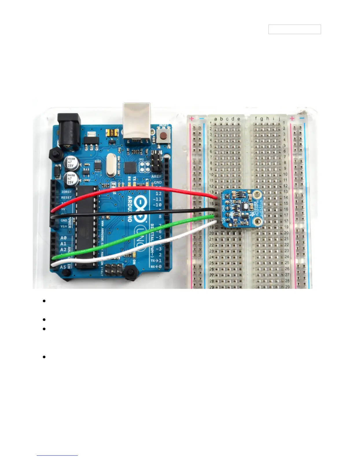
Connect Vin to the power supply, 3-5V is fine. Use the same voltage that the
microcontroller logic is based off of. For most Arduinos, that is 5V
Connect GND to common power/data ground
Connect the SCL pin to the I2C clock SCL pin on your Arduino. On an UNO & '328
based Arduino, this is also known as A5, on a Mega it is also known as digital 21 and
on a Leonardo/Micro, digital 3
Connect the SDA pin to the I2C data SDA pin on your Arduino. On an UNO & '328
based Arduino, this is also known as A4, on a Mega it is also known as digital 20 and
on a Leonardo/Micro, digital 2
The HTU21D-F has a default I2C address of 0x40 and cannot be changed!
Download Adafruit_HTU21DF
© Adafruit Industries
https://learn.adafruit.com/adafruit-htu21d-f-temperature-humidity-
sensor
Page 12 of 18
Question and Answer IconNeed help?

Do you have a question about the Adafruit Industries HTU21D-F and is the answer not in the manual?

Adafruit Industries HTU21D-F Specifications

General IconGeneral
Sensor TypeDigital Humidity and Temperature Sensor
Communication InterfaceI2C
Operating Voltage1.5V to 3.6V
Temperature Accuracy±0.3°C (at 25°C)
Temperature Range-40 to +125°C
Humidity Range0 to 100 %RH
Humidity Accuracy±2% RH
Response Time (humidity)8 seconds

Summary

Overview

Pinouts

Power Pins

Details the VIN, 3V3, and GND pins for powering the sensor and its voltage regulator.

I2C Logic pins

Explains the SCL and SDA pins required for I2C communication with the sensor.

Assembly

Prepare the header strip

Instructions for cutting and preparing the header strip for soldering to the breakout board.

Add the breakout board

Guide on positioning the breakout board over the header pins for soldering.

And Solder!

Steps for ensuring reliable electrical contact by soldering the pins to the board.

Wiring & Test

Download Adafruit HTU21DF

Load Demo

Steps to download the library and upload an example sketch to test the sensor.

Library Reference

Downloads

Files & Datasheets

Provides links to essential resources like datasheets, Fritzing objects, and PCB files.

Schematics

Presents the circuit schematic diagram for the HTU21D-F sensor breakout board.

PCB Print

Displays the physical dimensions and layout of the sensor's printed circuit board.