Lesson 5 Passive Buzzer
Introduction
The difference between an active buzzer and a passive one radically lies in the
requirement for input signals. The ideal signals for active buzzers are direct currents(DC),
usually marked with VCC or VDD. Inside them there are a simple oscillation circuit that
can convert constant direct currents into pulse signal of a certain frequency, causing
magnetic fields alternation and then Mo sheet vibrating and making sounds. On the other
hand, there is no driving circuit in a passive buzzer. So the ideal signal for passive buzzer
is square wave. If DC is given, it will not respond since the magnetic field is unchanged,
the vibration plate cannot vibrate and produce sounds.
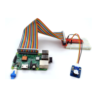
Components
- 1 * Raspberry Pi
- 1 * GPIO Extension Board
- 1 * 40-Pin GPIO Cable
- 1 * Breadboard
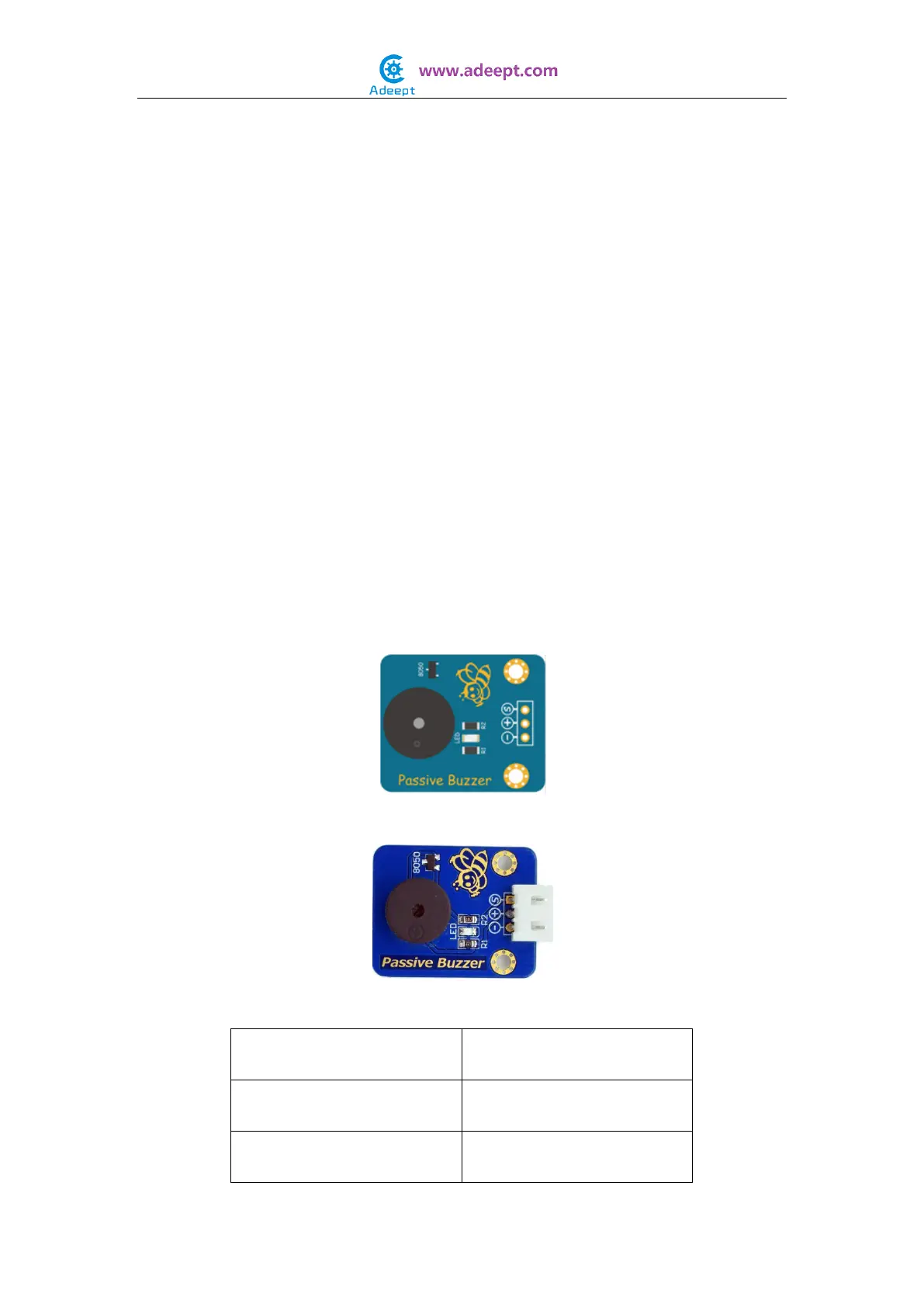
- 1 * Passive Buzzer Module
- 1 * 3-Pin Wires
Experimental Principle
The Fritzing image:
The Physical picture:
Pin definition: