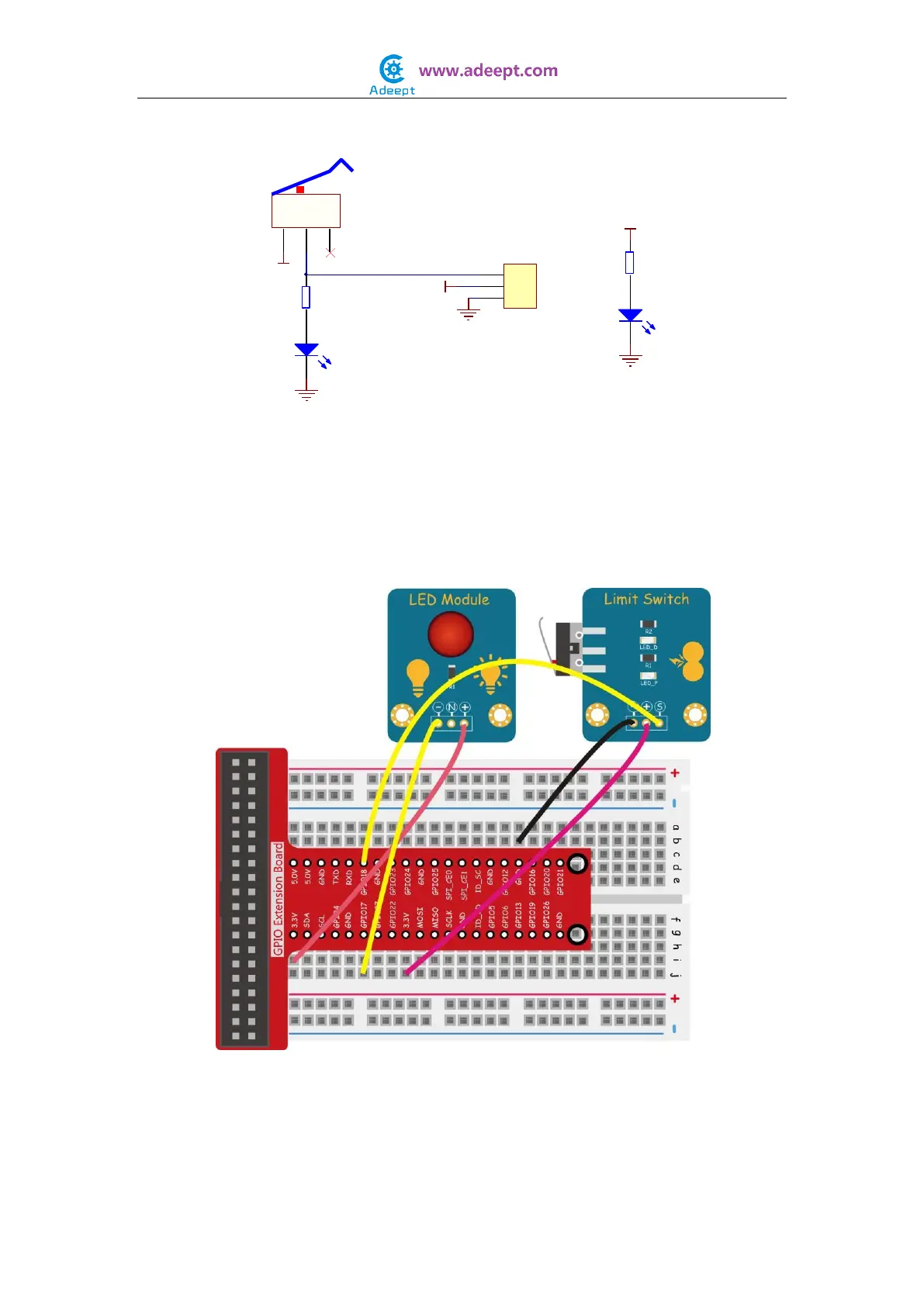
The schematic diagram:
In this experiment, by programming the Raspberry Pi, we detect the status of the Limit
Switch module through pin 12 of the Raspberry Pi and then toggle the LED based on the
output signal of the limit switch.
Experimental Procedures
Step 1: Build the circuit
For C language users:
Step 2: Edit and save the code with vim or nano.
(code path: /home/Adeept_Sensor_Kit_for_RPi_C_Code/12_limitSwitch/limitSwitch.c)
C
1
NO
2
NC
3
S1
Crash
LED_P
220Ω
R1
1
2
3
P1
Header
VCC
GND
GND
VCC
VCC
LED_D
1K
R2
GND
S
+
-