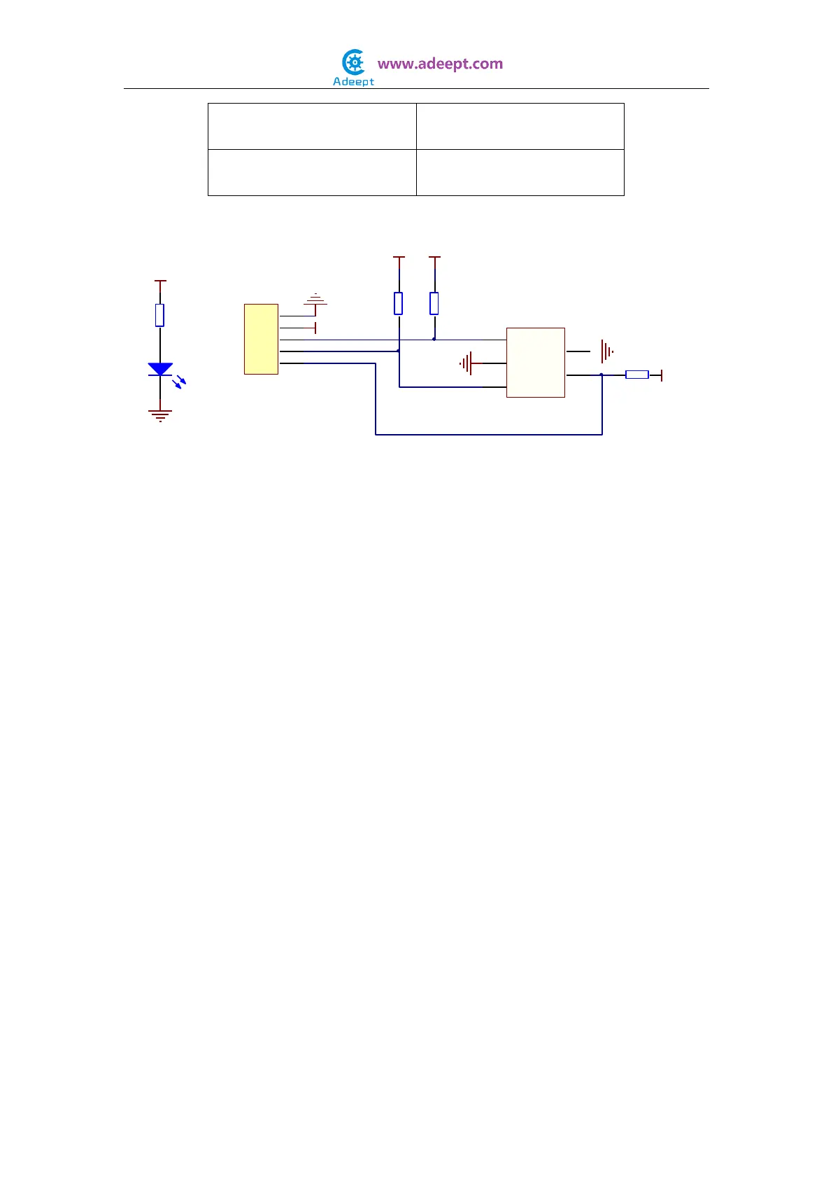
The schematic diagram:
In this experiment, by programming the Raspberry Pi, we change a value by reading the
status of the Rotary Encoder. When we turn the knob of the Rotary Encoder clockwise,
the value on the terminal will increase; when we turn the knob counterclockwise, the
value will decrease. When we press down the switch, the value will be zeroed out.
Experimental Procedures
Step 1: Build the circuit
1
2
3
4
5
P1
A
1
B
2
C
3
SW+
4
SW-
5
E1
Rotary Encoder
10K
R1
10K
R2
220Ω
R3
D1
LED
+
A
B
S
-
VCC
VCC VCC
VCC
VCC
10K
R4
GND
GND
GND
GND