Do you have a question about the ADEMCO 4140 and is the answer not in the manual?
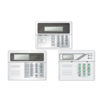
Lists and describes the available console types for the VISTA AT system.
Console with 12 backlit keys, alphanumeric LCD, and piezoelectric sounder.
Console with LCD display for zone ID and pre-defined words, piezoelectric sounder.
Detailed explanations for various zone types including Entry/Exit, Perimeter, Fire, and Silent alarms.
4-digit code for installation company use, allows entry into programming mode.
Code used to assign up to thirteen secondary codes for users.
Codes assigned by Master code for users 3-15, including temporary codes.
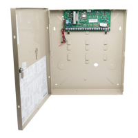
Instructions for mounting the digital communication interface board onto the main circuit board.
Details on connecting system components via terminal blocks.
Ensuring proper earth ground connection for lightning and electrostatic discharge protection.
Details for zone, console data, and return wiring terminals.
Details for DC input, earth ground, and Zone 1 fire connection terminals.
How to connect and operate an optional remote keyswitch for arming/disarming.
Instructions for connecting 4137 or 5137 consoles to the control unit.
Procedures for physically installing the system consoles.
Method for mounting consoles directly onto the wall surface.
Method for mounting consoles into a prepared wall opening.
Default programming values that can be accepted or altered by the installer.
Detailed guide for programming specific system addresses and functions.
Procedures for thoroughly testing all system functions after installation.
Adjusting the console display viewability for optimal user experience.
Accessing abbreviated system instructions stored in the console memory.
Instructions for explaining system operation and features to the end-user.
Procedure to display historical alarm and trouble events stored in memory.
Guidance on locating and replacing system fuses.
List of additional components available for system expansion and functionality.
Technical details and dimensions for system components.
Technical details and dimensions for the main security control unit.
Technical details for the remote consoles, including physical and electrical specs.
Detailed wiring instructions for connecting the optional remote keypad.
Information on the system's inherent limitations and potential failure points.
Details of the product warranty, terms, and conditions.
| Brand | ADEMCO |
|---|---|
| Model | 4140 |
| Category | Security System |
| Language | English |