N%&&l %92
74!5X3/ VOICE SIREN DRIVER
Features
. Generates voice output in Engbsh, French, and Spanish.
. Separate messages for FIRE and BURGLARY condtions.
. Separate siren sounds Ior FIRE and BURGWRY conditions.
. Terminal sttip for secure connection to wntrol panel.
. %lwQble input level (HigfdLow) for FIRE/BURGURY inputs.
. Supewision feature for s~aker and speker wiring
. Compatible with most conwol panels.
. Sounder options for kll ringbac~ell test.
. Com~tible with &160hm speakers.
, Operates on 12-16V DC.
. Small compact size for easy instillation using double-sidti tip
(packed separately) - measures Only 0 x 2-5/W x 1-1/4”.
Output Selection
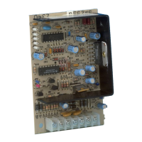
The voice dtiwr an be pogrammed for the desired alarm output
on burgla~ and fire by means of jumpers JPI through J~4, as
indicated in Table 1. %e Figure 1 for 10=tiOn of jUmPeH.
Table 1. Output Selatlon
X = CUT, —= INTACT
Bell Tes~lngback Options (JP5)
If jumper JP5 is kept intact, the siren diver will generate a steady
sound for bell test and bell tingback rnndtions.
If the jumper is cut, a warbled sound will be generated for bell
tesVtingback conditions. Note: If this mode is selected, a fire
signal will momentarily generate a warbled siren sound for the
initial poflion of the siren sound and then revefl to tie normal siren
sound and voim message.
Burgfaw Signal Polarity (JP6]
Intact = Mgh(i 2V+), mt = Low (OV).
The burglav message may be activated by either a sieady logic
high or a steady logic low, as provided by the control panel (refer
to the antrol pane~s instructions).
When jumper JP6 is intact, activation is by a logic high (12V+) at
terminal 2. Cut jum~r JP6 for activation by a logic low (OV). Note
that a pu/sing Mgh or low (pulse width 0.25 to 1.75 sewnds, that is
provided by some panels) connected to the BurglarylFire input
(terminal 2) will be interpreted as a Fire condition and will produe
the fire message.
Fire Signal Polarity (JP7)
Intact =Wgh(12V+), cut = Low (OV).
As in the case of Burglaw signal Platity, the fire message maybe
activated by either a logic high or logic low, but at terminal 3
(Ademco control panels provih a logic high). When jumper JP7 is
intact, activation is by a logic high (i 2V+). Cut jumper JP7 for
activation by a logic low (OV).
Burgla~ Wles=ges:
r
ENGLISH:
YOU HAVE VIOLATEO A PROTECTED AREA . . . THE POLICE
HAVE BEEN CALLEO . . . LEAVE IMMEDIATELY!
SPANISH:
USTEO HA VIOLA~ UNA AREA PROTWIOA . . LA POLICIA H1
sl~ LLAMP,DA . . .
SALGA IMMEOIATMENTE!
L
FRENCH:
VOUS AV= PENHRE UN LfEU SURVEILLE . . . LA POLICE A
ETE AVERTI . . ~AQUEZ IMMEOIATEMENT!
Burg/a~ A/arm Sequen@:
Warble Siren sound, Burglaw Voim Message (repeated 3 times),
1$semnd Warble Siren %und.
Sequence wtill r@peat until the Burglary output co~?dition is
terminat~.
Fire Messs!ges:
]
FUEGO . . . SALGA IMMEOIATEMENTE!
AU FEU! . . . EVAQUEZ IMMEDIATEMEN1!
Steady Shell Sound, Fire Vokce Message repeated 3 times on
single langu?~geoutput, followed by 15 seconds of Steady Siren
Se uence wil~ntil the Fire output condbion is terminated.
Wiring C0!3necti0ns
Witing connections to the terminals are as follows. Refer to Figure
1 (and Table 2 for Abmo prducls).
1 SUPW SF’EAKEWIRING SUPERVISION (OPTIONAL).
For supewision of the speaker and associated widng, connect to a
24-hour zonf that is activated by a shod.
Removing the speaker or shorting either speaker terminal to
ground will ,%ppearas a shorn on the zone. Note that in seties-
mnnected w,ultiple speaker systems, cutting any speaker will tip
the antrol p~nel,s supewision zone. In parallel-mnnetied speaker
systems, each branch must be cut before the control panel’s
supervision 20ne will hip.
2 WE BURGURY/FIRE INPUT:
Connect thc~ control pane~s Burglary (steady) output to this
terminal. Tti:s terminal may also be used to rip the FIRE message
if tie control provihs a pulsing output for fire (re-program[ming may
be requird). In this ase, no connection to terminal 3 is r<?quir~.
3 F: F/RE //VPUT:
Connect the control DaneVsoutDut designated as the FIRE (steady)
vol~ge outptlt to thi; terminal (unless t~s output was cotlnicted to
terminal 2).
4 SPKR& 5 !jPKR: SPEAKER TERMINALS:
Connect an E-ohm or <6-ohm 15-watf speaker to tiese terminals.
See Rgure 3 for multiple speaker configurations.
6 (+} 12VDC(+) POWER /NPUT:
Connect to a
12VDC (+) sour~ on the anwol; sine the dtiver can
draw as muf:h as 1.i imps, it may be necessay in some cases
(see Table 2 for Ademco products) to connect to the system’s
back-up batb?w through a 2 amp in-fine fuse, as shown in Figure 2.
7 (-): 12VDC(-) POWER INPUT:
Corm-l to a gro.”d point (–) on the control pmel.
I
Speakers: 15-watt s~akers.
Sound Output: 106dB @ 10 ft.
Current Dralm
1
8-ohm Speakec 1100 mA (steady siren)
(at 12V
Oc) 12@hm Speakefi 950 mA (steady siren)
)6-ohm Speakec 800 mA (steady siren
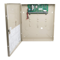
fmpotiant: ‘We recommend that the Voice Siren Driver be
mount~ in <hecontrol cabinet, not remotely.