Industrial Electronic Devices
ADFweb.com Srl – IT31010 – Mareno – Treviso INFO: www.adfweb.com Phone +39.0438.30.91.31
Document code: MN67619_ENG Revision 1.000 Page 16 of 25
S7comm ACCESS:
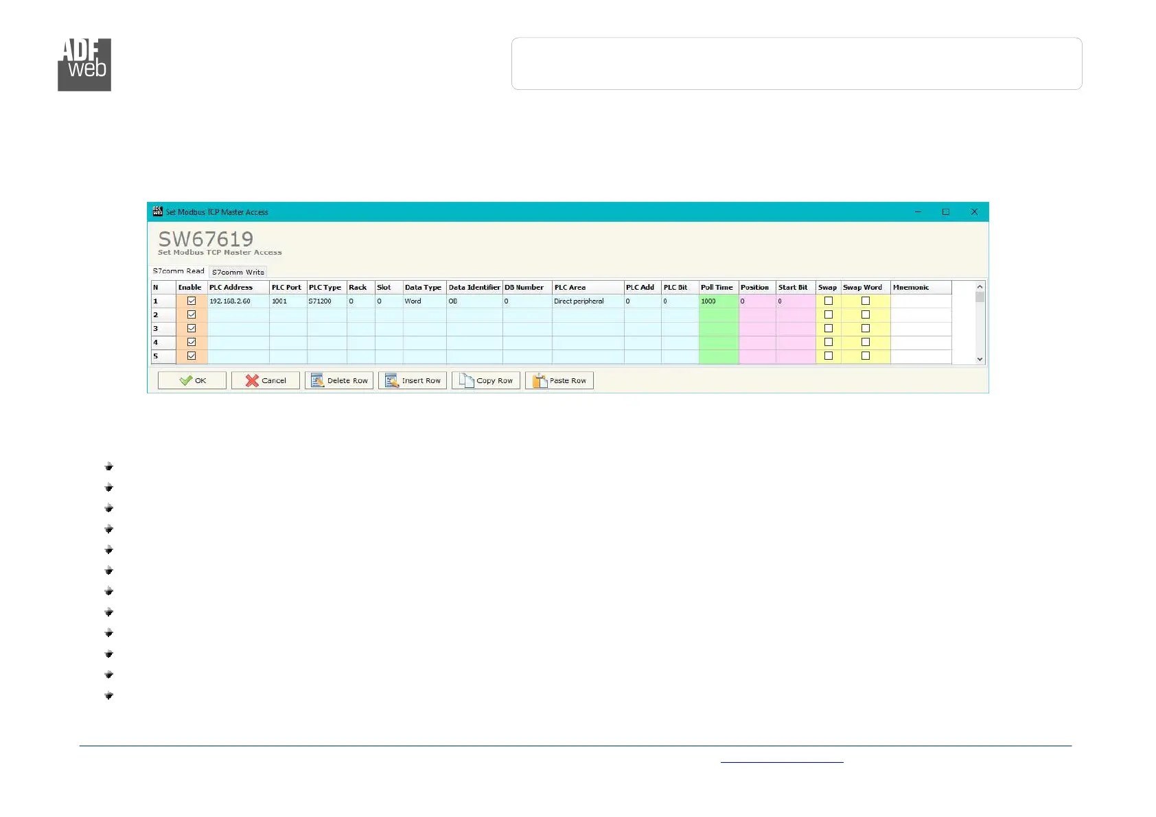
By Pressing the “S7comm Access ” button from the main window of SW67619 (Fig. 2), the window “Set S7comm Access” appears (Fig. 4).
The window is divided in two parts, the “S7comm Read” that contains the data that the converter reads from the S7comm servers and
“S7comm Write” that contains the data that the converter writes into the S7comm servers.
The means of the fields in the window “S7comm Read” are the following:
In the field “PLC Address” the IP address of the PLC that contains the data to be read is defined;
In the field “PLC Port” the port used for S7comm communication is defined;
In the field “PLC Type” the family of the PLC is defined;
In the field “Rack” the Rack’s ID of the PLC is defined;
In the field “Slot” the Slot’s ID is defined;
In the field “Data Type” the data format of the variable to read is defined;
In the field “Data Identifier” the identifier of the variable to read is defined;
In the field “PLC Area” the memory area where the data is located inside the PLC is defined;
In the field “PLC Add” the starting memory address where the data is located is defined;
In the field “PLC Bit” the starting bit of the selected PLC Address is defined;
In the field “Poll Time” the frequency of the request is defined (in ms);
In the field “Position” the starting byte of the PROFIBUS array from which mapping the data read is defined;