Industrial Electronic Devices
ADFweb.com Srl – IT31010 – Mareno – Treviso INFO: www.adfweb.com Phone +39.0438.30.91.31
Document code: MN67619_ENG Revision 1.000 Page 18 of 25
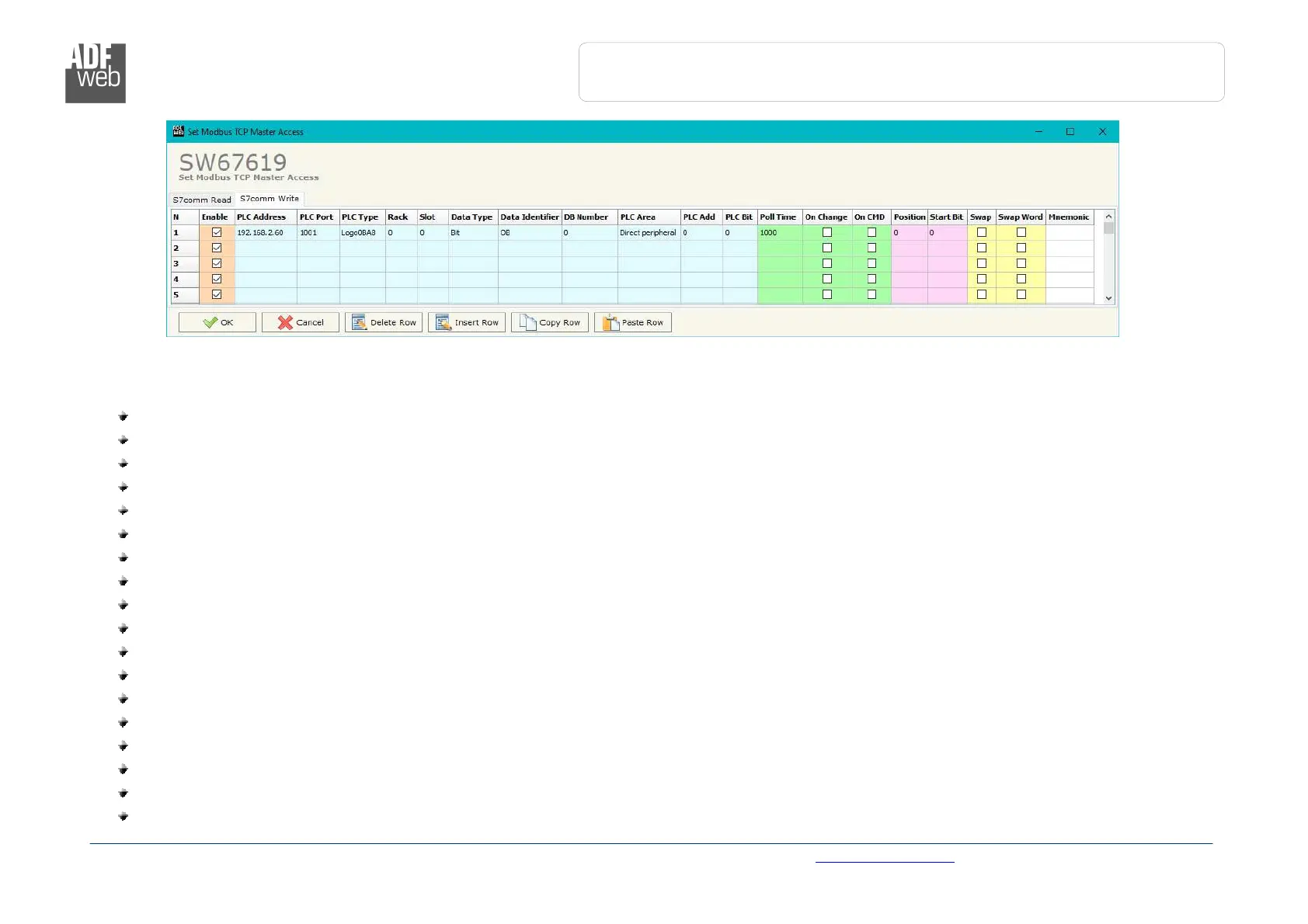
Figure 4b: “S7 Protocol Access
S7comm Write” window
The means of the fields in the window “S7comm Read” are the following:
In the field “PLC Address” the IP address of the PLC that contains the data to be read is defined;
In the field “PLC Port” the port used for S7comm communication is defined;
In the field “PLC Type” the family of the PLC is defined;
In the field “Rack” the Rack’s ID of the PLC is defined;
In the field “Slot” the Slot’s ID is defined;
In the field “Data Type” the data format of the variable to read is defined;
In the field “Data Identifier” the identifier of the variable to read is defined;
In the field “PLC Area” the memory area where the data is located inside the PLC is defined;
In the field “PLC Add” the starting memory address where the data is located is defined;
In the field “PLC Bit” the starting bit of the selected PLC Address is defined;
In the field “Poll Time” the frequency of the request is defined (in ms);
By checking the field “On Change” the S7comm write request is sent only if PROFIBUS data are changed;
By checking the field “On CMD” the S7comm write request is sent when a PROFIBUS writing for the selected variable is received;
In the field “Position” the starting byte of the PROFIBUS array from which taking the data to write is defined;
The field “Start Bit” is used for the “Bit” data. It is possible to select the bit of the selected Position from which taking the data;
If the field “Swap” is checked, the bytes’ order is reversed;
If the field “Swap W” is checked, the words’ order is reversed;
In the field “Mnemonic” a description of the data inserted in the row is defined.