IRF2000 series - standard Doc v2.7 33
© ads-tec Industrial IT GmbH • Heinrich-Hertz-Str. 1 • 72622 Nürtingen • Germany
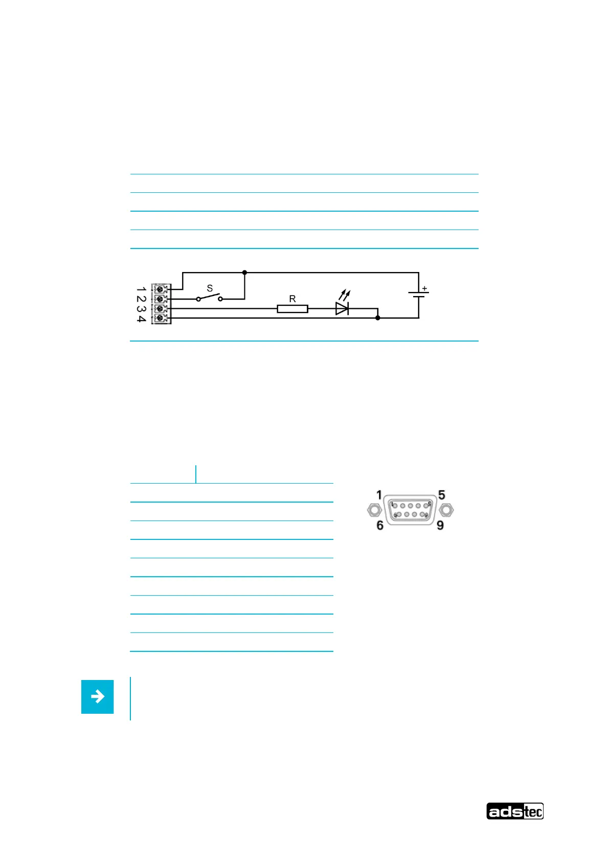
6.4.5 CUT & ALARM
With the help of a key switch at the IN (CUT) input, the WAN connection(s) can be blocked and
released again (i.e. in most cases Internet access).
The OUT (ALARM) output indicates that the WAN port(s) have been blocked.
The CUT&ALARM connector is internally galvanically isolated from the power supply of the device.
1 +24 VDC ± 20 %
2 IN (CUT): +24 VDC ± 20 %, max. 16 mA
3 OUT (ALARM): +24 VDC ± 20 %, max. 1 A
4 Reference potential (GND)
(Schematic circuit diagram, picture shows socket in device)
6.4.6 Serial interface COM (RS232)
The serial interface is used for digital data transmission. The RS232 interface can be connected by
using a commercially available 9-pin SUB-D cable.
Pin Signal
1 DCD
2 RxD
3 TxD
4 DTR
5 GND
6 DSR
7 RTS
8 CTS
9 RI
This interface is not electrically isolated.
 Loading...