–
8
–
Configurable Zone Types Worksheets
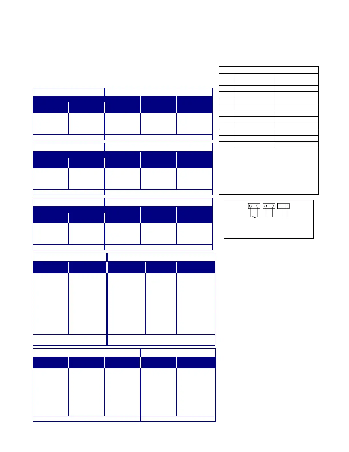
Configurable zone types 90 and 91 can be programmed via downloader software or from a touchpad using data
fields*182-*185. Configurable zone types 92 and 93 can only be programmed using the downloader software.
Programming Configurable Zone Type options involves entering 10 digits in data field *182 for zone type 90 and
field *184 for zone type 91, where each digit represents the sum of the values of its various options as shown in
the tables below. Use fields *183 and *185 to program Contact ID
®
report codes for these zone types.
RF ZONE NOTE:
The “open” option in digits 1, 3, and 5 is not applicable
for RF zones. Use the “intact EOL” option for normal RF zone conditions
and “shorted” for off-normal RF zone conditions.
DIGIT 1 DIGIT 2
Response when system disarmed and zone is:
Intact EOL
RF zone normal
Open
RF zone N/A
Shorted
RF zn off-normal
Auto
Restore Vent Zone
0 = normal
1 = alarm
2 = trouble
3 = fault
0 = normal
4 = alarm
8 = trouble
12 = fault
0 = normal
1 = alarm
2 = trouble
3 = fault
0 = no
4 = yes
0 = no
8 = yes
Digit 1 = EOL + Open Digit 2 = Short + auto restore + vent zone
DIGIT 3 DIGIT 4
Response when armed STAY and zone is:
Intact EOL
RF zone normal
Open
RF zone N/A
Shorted
RF zn off-normal
Byp. when
disarmed
Byp. when
armed
0 = normal
1 = alarm
2 = trouble
3 = fault
0 = normal
4 = alarm
8 = trouble
12 = fault
0 = normal
1 = alarm
2 = trouble
3 = fault
0 = no
4 = yes
0 = no
8 = yes
Digit 3 = EOL + Open Digit 4 = Short + byp. disarmed + byp. armed
DIGIT 5 DIGIT 6
Response when armed AWAY and zone is:
Intact EOL
RF zone normal
Open
RF zone N/A
Shorted
RF zn off-normal
Dial Delay
(see field *50)
Fault Delay
(see field *53)
0 = normal
1 = alarm
2 = trouble
3 = fault
0 = normal
4 = alarm
8 = trouble
12 = fault
0 = normal
1 = alarm
2 = trouble
3 = fault
0 = no
4 = use delay
0 = no
8 = use delay
see note 1
Digit 5 = EOL + Open Digit 6 = Short + dial delay + fault delay
DIGIT 7 DIGIT 8
Display Faults Power Reset/
Verification
Use Entry
Delay 1/2
Use Exit
Delay
Respond as
Interior Type
0 = show alarms
when armed
& disarmed
1 = don’t show
alarms when
armed
(show
alarms, trbles,
faults when
disarmed)
3 = never show
any alarms,
trbles, faults
0 = no
4 = power reset
after fault
(by code + OFF)
12 = verification
(see zone
type 16)
0 = no
1 = delay 1
2 = delay 2
0 = no
4 = use exit
delay
0 = no
8 = yes
see note 2
Digit 7 = fault display + power
reset/verification
Digit 8 = entry delay 1/entry delay 2 + exit delay +
interior zone type
DIGIT 9 DIGIT 10
Alarm Sounds Use Bell
Timeout
Respond as
Fire Zone
Trouble
Sounds
Chime when
Chime Mode On
0 = none
1 = steady
touchpad
2 = steady bell
and
touchpad
3 = pulsing bell
and
touchpad
0 = no
4 = yes
see fields *32,
*33
0 = no
8 = yes
see zone type
09; see note 4
0 = none
1 = periodic
beep
2 = trouble
beeps
0 = no
4 = yes
Digit 9 = alarm sounds + bell timeout + fire zone Digit 10 = trouble sounds + chime
Entries for Fields *182 and *184
Digit Zone Type 90 Zone Type 91
(field *182) (field *184)
1
2
3
4
5
6
7
8
9
10
To calculate each digit’s entry:
Simply add the values of the selected options
in each of the digit’s columns (one option per
column). For example, to program Digit 2 for
“alarm response to short,” “auto restore on,”
but not a “vent zone,” enter 5 (“1” for alarm
short + “4” for auto restore yes + “0” for vent
zone no).
OPEN SHORTEDINTACT
EOL
ADT3000-018-V0
Zone Conditions Represented
in Digits 1-6
NOTES:
1. Do not use the “fault delay” option with a
configurable zone type if it is set for an
entry or exit delay, otherwise
unpredictable results may occur.
2. To create an interior type zone, select
“respond as interior zone type” (Digit 8,
interior type = yes), and set zone
response to “fault” in digits 3-4 to ensure
fault displays; do not set as “normal,”
“alarm,” or “trouble.”
3. Do not set fire zones to respond as a
“fault” (digits 1-6), otherwise faults will not
display unless the [
∗
] key is pressed.
4. 4219/4229 modules must use EOLRs or
unpredictable results may occur.

 Loading...