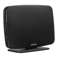
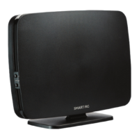
8612 and 8614 Router QSG Installing the SDG-8612 and SDG-8614 Router
6SDG861214-13A 3
Supplying Power to the Device
The SDG-8612 and SDG-8614 comes with a region specific AC to USB-C power adapter. Available regions include: North America, United
Kingdom, EU, and Australia/New Zealand.
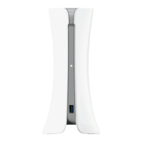
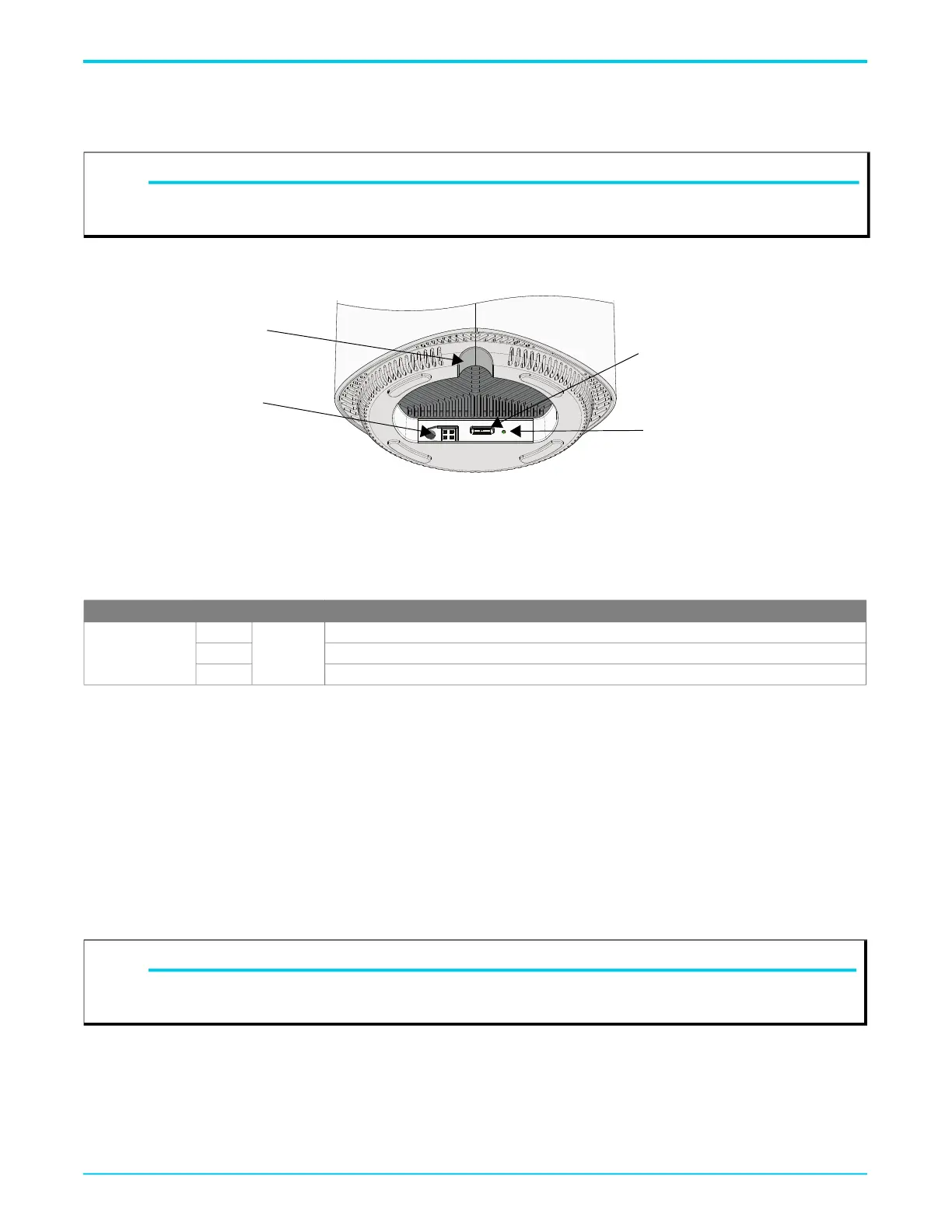
Power is supplied to the SDG-8612 and SDG-8614 via a USB-C power input connector located on the bottom of the SDG (see Figure 2).
Figure 2. SDG-8612 and SDG-8614 Bottom View
1. Connect the USB-C end of the power adapter to the USB-C Power In Port on the bottom of the device.
2. Plug the other end of the power adapter into the wall outlet.
3. The SDG will begin powering up immediately as the SDG-8612 and SDG-8614 have no on/off power switch.
4. Confirm that the power is connected properly by checking the Power LED located to the right of the Power In port.
5. The Multifunction Status LED should be lit on the front of the device, as described in the following section “Multifunction Status LED”.
Subscriber Connections
The following subscriber connections are available on the SDG-8612 and SDG-8614:
■ 2.5G Ethernet interface (RJ-45 connector) - WAN port (SDG-8612 only)
■ SFP+ cage - WAN port (SDG-8614 only). Maximum power output capability is 2.7W.
■ 2.5G Ethernet interface (RJ-45 connector) - LAN port
■ 3x Ethernet port (RJ-45 connector) – LAN port
■ USB 3.0 (Type A Connector)
To connect the Ethernet interfaces, refer to Figure 1 on page 1 and insert a Category 5E (or better) RJ-45 cable into The WAN port on the SDG-
8612 and any LAN port until there is an audible click.
To install a SFP+ into the SDG-8614, complete the following steps:
1. Insert the SFP+ into the SFP+ cage on the device.
2. Slide the SFP+ all the way into the SFP+cage until there is an audible click.
The USB 3.0 host port is reserved for future use. This port currently provides +5 VDC for charging external devices.
NOTE
g
3rd party USB-C power supplies are not recommended for use as they may not provide the required USB power delivery profile for the
SDG-8612 and SDG-8614 units.
LED Color State Description
Power
Green
Solid
Correct Power
Red Incorrect Power
Off No Power
NOTE
g
Only CDRH certified laser class I (1) optical transceivers must be used when connecting an optical transceiver to the SFP+ cage. Do not
remove the protective dust cover from the SFP+ until the fiber optic cable is ready to be connected.
Console Port
(shown here without rubber flap
cover)
USB-C Power In Port
Power LED
Routing Hole for
Power Cable