Do you have a question about the ADTRAN GPON TA352 and is the answer not in the manual?
Read all warnings and cautions before installing or servicing equipment. Includes fiber cable and NID cautions.
Lists essential tools and supplies for installation, including specialized items for fiber and electrical connections.
Outlines the sequence of steps for ONT installation, from unpacking to connecting services.
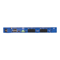
Identifies the four input ports on the NID enclosure for service entry and protection from elements.
Instructions for mounting the NID enclosure to a surface and installing the protective ground connection.
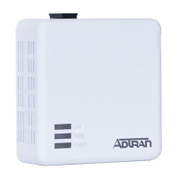
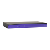
Guidance on aligning and snapping the ONT unit into the NID housing, noting model differences.
Cautions regarding metallic trace wires, proper routing, and cleaning optical surfaces for safe fiber connection.
Emphasizes cleaning all optical surfaces before connecting cables to ensure optimal performance and prevent damage.
Steps to safely connect the 7-pin Power/Alarm connector to the ONT, including wiring notes and power warnings.
Details requirements for local power sources and UPS, including warnings on power supply type and line cord gauge.
Instructions for routing and terminating POTS and Ethernet cables to the appropriate ports on the ONT.
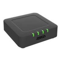
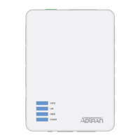
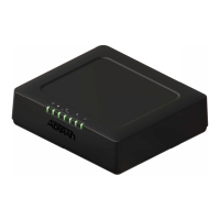
Provides a table explaining the meaning of each LED status indicator on the ONT for troubleshooting.
Explains methods for registering the ONT, including using a lineman's handset and relevant notes on timing and format.
Comprehensive specifications covering electrical, optical, physical, and environmental aspects of the ONT.
Information on maintenance, field repair limitations, and references to safety and regulatory compliance documents.
| Input Power Connection | UPS provided through 7-pin alarm connector |
|---|---|
| Voltage Range | 12 VDC nominal |
| Minimum Voltage | 10 V |
| Maximum Voltage | 16 V |
| Power Consumption | Less than 15 W |
| TX min power | 0.5 dBm |
|---|---|
| TX max power | 5.0 dBm |
| RSSI max sensitivity | –27.0 dBm |
| RX overload | –8.0 dBm |
| TX wavelength | 1310 nm typical |
| RX wavelength | 1490 nm typical |
| Height | 9.05 in. (23.0 cm) |
|---|---|
| Width | 8.66 in. (22.0 cm) |
| Depth | 1.38 in. (3.5 cm) |
| Weight | 3.5 lbs. (1.6 kg NID and ONT combined) |
| Operational Temperature Range | –40°C to +65°C |
|---|---|
| Storage Temperature Range | –40°C to +85°C |
| Relative Humidity | 95% (non-condensing) |