For more detailed documentation, visit us online at www.adtran.com
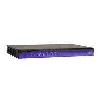
NETVANTA 4305 (SYSTEM) P/N 1200890L1
Quick Start Guide
Quick Start Guide, 61200890L1-13A, June 2004 Technical Support 1-888-4ADTRAN (1-888-423-8726) © 2004 ADTRAN, All Rights Reserved
INSTALL THE NETWORK INTERFACE MODULE (NIM)
1. Verify the unit is not connected to a power source.
2. (Optional) To install the Dial Backup Interface Module (DIM), carefully align
the P1 connector on the NIM with the J1 connector on the DIM. Using only
fingertip pressure to ensure that neither circuit board bends or flexes, firmly
seat the connectors. Secure the DIM to the NIM using the supplied screws
and standoff posts.
3. Slide the NIM into the option slot until the module is firmly positioned against
the back of the chassis.
4. Secure the push pins at both edges of the module.
5. (Optional) To install the Wide Slot Interface Module, align the module with
Slot 3 and slide the module into the chassis until it is firmly positioned
against the backplane connectors. Secure by tightening the screws.
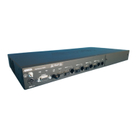
CONNECT TO THE NETVANTA 4305 CONSOLE
Before connecting to the NetVanta 4305 CONSOLE interface you will need the
following items: VT100 terminal or PC (with VT100 terminal emulation software)
and a straight-through serial cable with a DB-9 (male) connector on one end and
the appropriate interface for your terminal (or PC) on the other.
1. Connect the DB-9 (male) connector of your serial cable to the CONSOLE
port on the rear panel of the unit.
2. Connect the loose end of the serial cable to the VT100 terminal or PC (with
terminal emulation software).
3. Open a VT100 terminal session to the NetVanta 4305 using the following
settings:
9600 baud, 8 data bits, no parity bits, and 1 stop bit. Press <Enter> to
activate the ADTRAN Command Line Interface.
4. Enter enable at the > prompt.
5. Enter the password when prompted. The default password is password.
LED DESCRIPTIONS
For these
LEDs…
This
activity…
Indicates that…
STATUS
Green
(blinking)
Unit is powering up. On power-up the STAT LED blinks rapidly
for five seconds, during which time the user may escape to boot
mode from the console port.
Green (solid) Power is on and self-test passed.
Red (solid)
Power is on, but the self-test failed or the boot mode (if
applicable) code could not be booted.
Yellow (solid) Unit is in test.
NET 1/ NET 2
WAN
Off No NIM is installed, or interface is administratively down.
Green (solid) Link is up and everything is operational.
Red (solid)
An alarm condition is occurring on the WAN interface, or there
is a self-test failure.
Yellow (solid) Unit is in test.
NET 1/ NET 2
DBU
Off No DIM is installed.
Green (solid)
DIM is ready. For the ISDN BRI DIM, green solid indicates that
the negotiation with the switch is complete.
Green
(blinking)
Unit is in dial backup.
Red (solid)
An alarm condition is occurring on the DBU interface, or there is
a self-test failure.
Yellow (solid) Unit is in test.
NET 1/NET 2
TD/RD
Green
(blinking)
There is activity on the WAN or DBU port.
Off There is no activity on the WAN or DBU port.
LAN 1/ LAN 2
LNK
Green (solid) 10BaseT Ethernet link is up.
Yellow (solid) 100BaseT Ethernet link is up.
LAN 1/ LAN 2
TD/RD
Green
(blinking)
There is activity on the Ethernet port.
Off There is no activity on the Ethernet port.
STATUS
NET 2
WAN
DBU
TD
RD
TD
RD
LNK
LAN 2
NetVanta 4305
STATUS
ACTIVITY
TEST
WIDE SLOT 1
TD
RD
LNK
LAN 1
NET 1
WAN
DBU
TD
RD