2.7.3 Detector Loop Installation
Maximum of 32 Sensors / Call Points in a Zone (between Isolators).
The Detection Loop Circuit should be installed as a continuous loop with isolator
modules such that a short circuit condition does not remove more than one zone or 32
input devices.
Refer to Section 5.5.4 for details on the use of Apollo Isolators.
Not more than 512 fire detectors and / or manual call points and their associated
mandatory functions shall be affected as a result of a system fault in the C.I.E.
The panel (or each chassis in the Mx-4800) should be installed with not more than 512
fire input devices.
See Appendix 9 for further details on Mx-4800 and network installations.
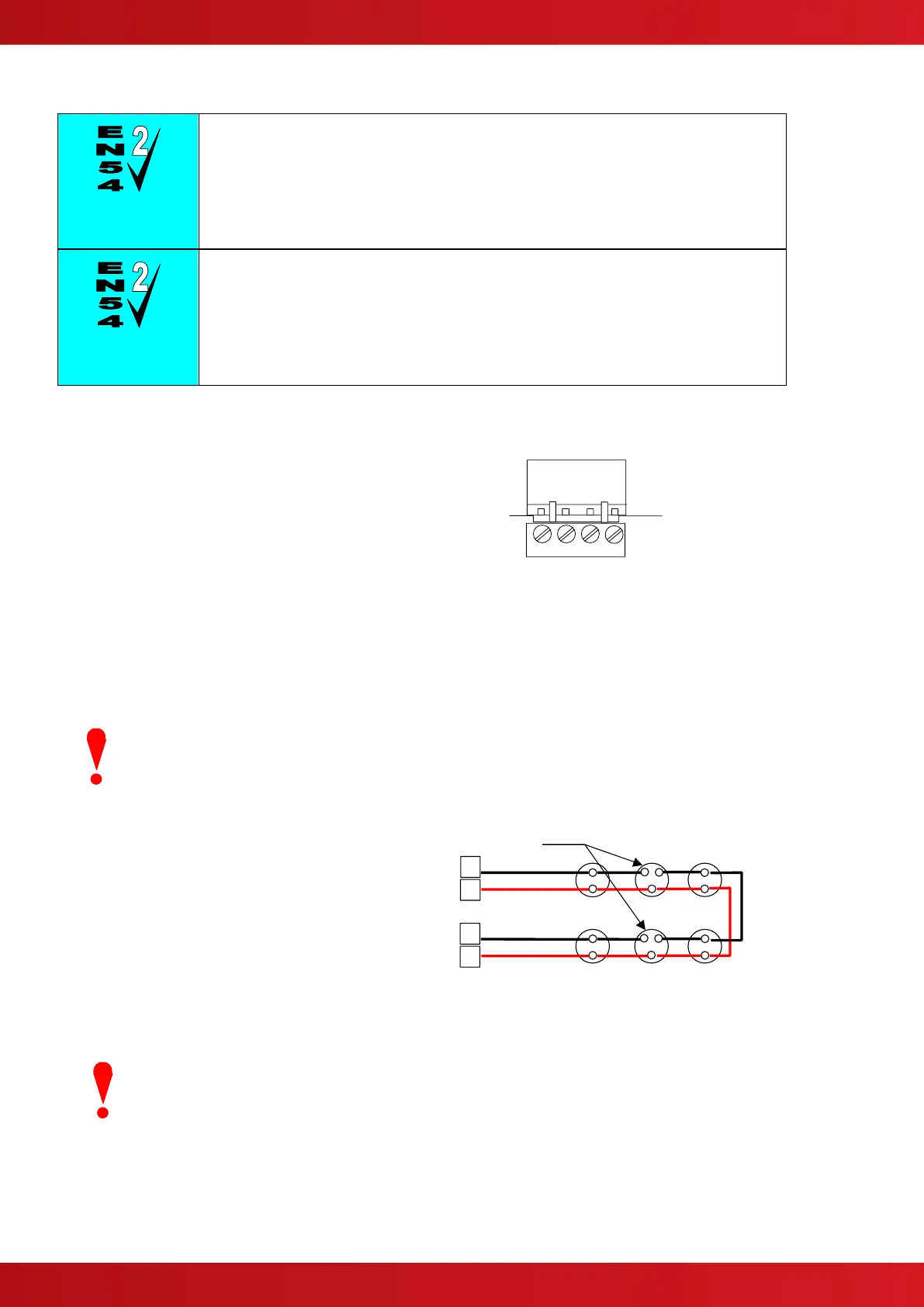
Form the loop starting at the Loop Out + and –
terminals on the base card.
Route the wires around the loop connecting all
devices in accordance with the manufacturers’
data sheet supplied with each unit.
Ensure that the devices are correctly installed with
regard to their positive and negative terminal
polarity (especially Loop Isolator Modules).
Connect the return wires to the Loop IN + and –
terminals on the base card.
The diagram opposite shows the typical
arrangement of the loop connections on the base
cards.
Refer to Section 2.5 for details on installing
additional loop drivers on the multi-loop panels.
Base Card Terminations (Typical).
It is recommended that shielded cable is used for the loops.
When screened cable is used, it is vital to connect the screen / drain wire to the chassis / earth at
the cable gland input / earth stud in the panel. Always ensure that all segments of the cable loop
have continuity of the screen and take care to ensure that the screen is not exposed to any other
earth point (e.g. metalwork, cable trays, junction boxes, etc.).
The Loop Driver Circuit on the Base card is
equipped with in-built isolators to take care of
short circuit conditions on the wiring between the
panel and the first device on the loop. Do not fit
loop isolators at the panel outputs.
The diagram opposite shows a typical loop
arrangement.
Maximum recommended cable loop length is 1500
to 2000 Metres. Refer to Appendix 2 –
Recommended Fire Rated Cables for further
information on cable types to be used.
Typical Loop Arrangement.
Take care that the voltage drop at full load is within the detector rating – refer to the detector
manufacturers’ data sheet for minimum values.
To maintain signal line wiring supervision, break the wiring run at each loop device.